EasyManua.ls Logo

Technische Alternative UVR61-3 User Manual

Technische Alternative UVR61-3
124 pages
To Next Page IconTo Next Page
To Previous Page IconTo Previous Page
Page #49 background imageLoading...
Page #49 background image
49
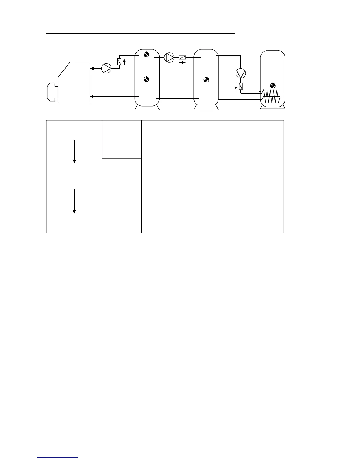
Program 576 - Cascade: S4 S1 S2 + burner requirement
Program 576: Feed pump A1 runs when:
S1 is greater than the threshold min1 and S1 is greater than S2 by the difference diff1
and S2 has not exceeded the threshold max1.
The feed pump A2 runs when:
S4 is greater than the threshold min2 and S4 is greater than S1 by the difference diff2
and S1 has not exceeded the threshold max2.
Output A3 switches on when S4 falls below threshold min3.
Output
A3 switches off (dominant) when S3 exceeds max3.
A1 = S1 > (S2 + diff1) & S1 > min1 & S2 < max1
A2 = S4 > (S1 + diff2) & S4 > min2 & S1 < max2
A3 (on) = S4 < min3 A3 (off) = S3 > max3
All programs +1:
The burner requirement (A3) only occurs via sensor S4.
A3 (on) = S4 < min3 A3 (off) = S4 > max3 (dominant)
Required settings:
max1 … limit CYL 3 S2 A1
max2 … limit CYL 2 S1 A2
max3 … burner req. off CYL 1 S3 A3
min1 … switch-on temp. CYL 2 S1 A1
min2 … switch-on temp. CYL 1 S4 A2
min3 … burner req. on CYL 1 S4
A3
diff1 … CYL 2 S1 – CYL 3 S2 A1
diff2 … CYL 1 S4 – CYL 2 S1 A2
S4
min2
S1
max2
min1
S2
max1
diff1
A1
diff2
A2
Burner
A3
S4 min3
S3 max3
A1
A3
S3
S4
S1
S2
CYL 1 CYL 2
CYL 3

Table of Contents

Other manuals for Technische Alternative UVR61-3

Questions and Answers:

Technische Alternative UVR61-3 Specifications

General IconGeneral
BrandTechnische Alternative
ModelUVR61-3
CategoryDryer
LanguageEnglish

Summary

Safety requirements

Maintenance

Details on how to maintain the system, including cleaning instructions and spare parts correspondence.

Generally applicable rules for the proper use of this unit

Rules for proper use, including specific guidance for swimming pool and solar thermal systems.

Setting for "Step by step" control

Hydraulic diagrams

Installation instructions

Installing the sensors

Guidance on proper arrangement and installation of sensors for system functionality.

Sensor lines

Information on extending sensor lines and proper connection techniques to prevent measurement fluctuations.

Installing the unit

Instructions for safely opening the unit case and mounting it to a wall.

Electrical connection

Guidelines for electrical connection by a professional electrician, including safety notes.

Special connections

Details on control outputs, sensor input S6, data link, and switching output 3 to potential-free.

Operation

The main level

Overview of the main display level, including icons for temperature, volume flow, and status.

Changing a value (parameter)

Procedure for changing parameter values using navigation keys and saving changes.

The parameter menu Par

Overview of the parameter menu, including code entry, version, program number, and settings.

Brief description

Explanation of parameter menu items like CODE, VER, PR, LO, PA, and set value types.

The menu Men

Brief description

Description of menu functions like ENGL, CODE, SENSOR, SYS PF, STARTF, PRIOR, ART, PSC, COP, F CHCK, HQC, LEGION, EXT DL, DRAINB.