EasyManua.ls Logo

Technische Alternative UVR61-3 User Manual

Technische Alternative UVR61-3
124 pages
To Next Page IconTo Next Page
To Previous Page IconTo Previous Page
Page #12 background imageLoading...
Page #12 background image
12
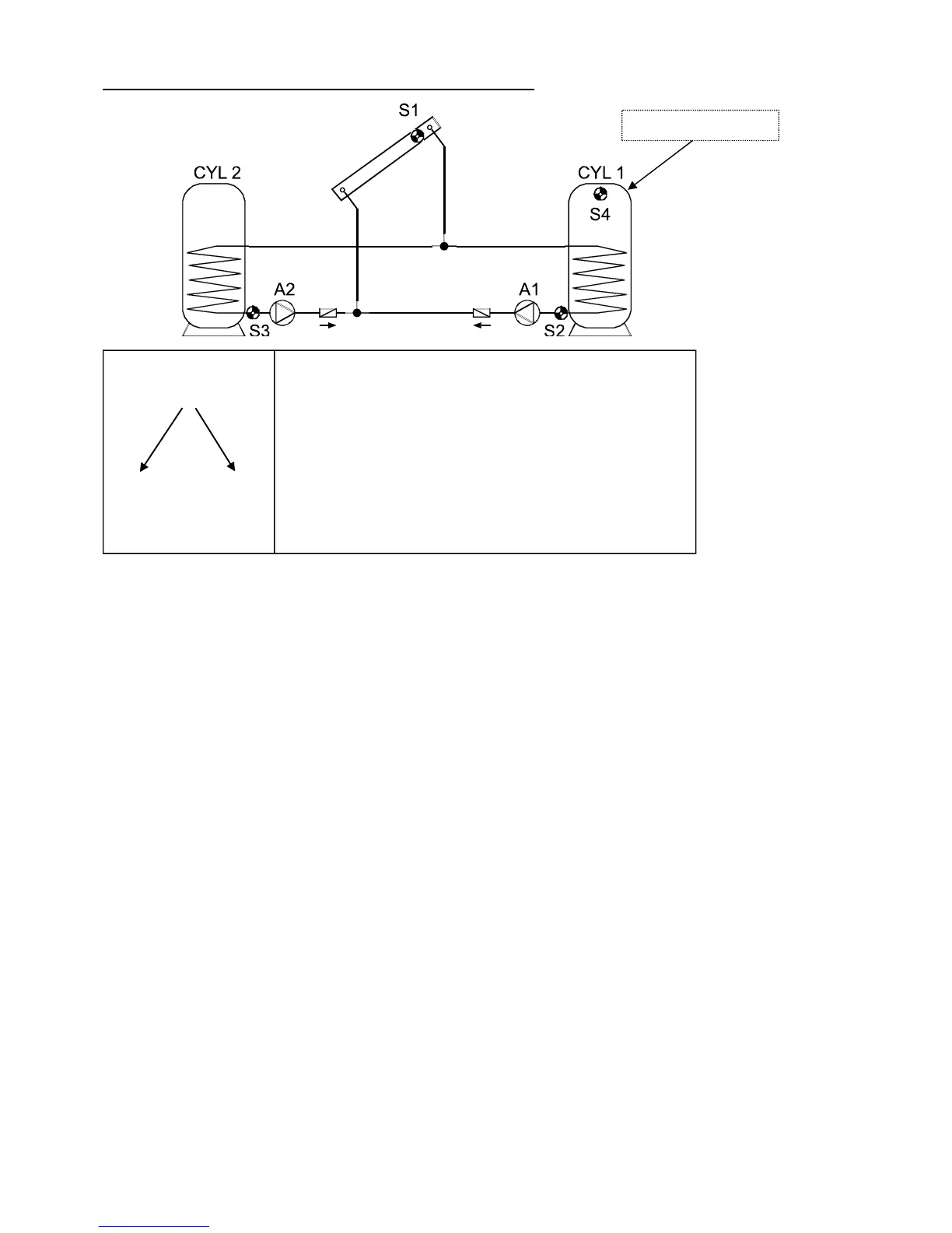
Program 48 - Solar power system with 2 consumers
Program 48: Pump A1 runs when:
S1 is greater than the threshold min1 and S1 is greater than S2 by the difference diff1
and S2 has not exceeded the threshold max1.
Pump A2 runs when:
S1 is greater than the threshold min1 and S1 is greater than S3 by the difference diff2
and S3 has not exceeded the threshold max2.
A1 = S1 > (S2 + diff1) & S1 > min1 & S2 < max1
A2 = S1 > (S3 + diff2) & S1 > min1 & S3 < max2
All programs +1:
Instead of the two pumps, one pump and a three-way valve are used (pump-valve system).
Speed control: Observe the comments on page 9!
Without a priority allocation, cylinder 2 is filled by priority.
A1 ... common pump A2 ... Valve (A2/S receives power when filling cylinder CYL 2)
All programs +2:
In addition, if S4 exceeds the threshold max3, pump A1 is switched off.
All programs +4: Both solar loops have separate switch-on thresholds at S1:
output A1 retains min1, and A2 switches at min2.
The priorities for CYL 1 and CYL 2 can be set in the parameter menu under PA. In addition,
a solar priority function can be set for this diagram in the menu PRIOR (see “solar priorities”
for more details).
S1
min1
S2 S3
max1 max2
diff2
A2
diff1
A1
Required settings:
max1 … limit CYL 1 S2 A1
max2 … limit CYL 2 S3 A2
max3 … see all programs +2
min1 … switch-on temp. coll. S1 A1, A2
min2 … see all programs +4
diff1 … coll. S1 – CYL 1 S2 A1
diff2 … coll. S1 – CYL 2 S3 A2
CET 1 ... OP 1 OP 12
S4 for program +2

Table of Contents

Other manuals for Technische Alternative UVR61-3

Questions and Answers:

Technische Alternative UVR61-3 Specifications

General IconGeneral
BrandTechnische Alternative
ModelUVR61-3
CategoryDryer
LanguageEnglish

Summary

Safety requirements

Maintenance

Details on how to maintain the system, including cleaning instructions and spare parts correspondence.

Generally applicable rules for the proper use of this unit

Rules for proper use, including specific guidance for swimming pool and solar thermal systems.

Setting for "Step by step" control

Hydraulic diagrams

Installation instructions

Installing the sensors

Guidance on proper arrangement and installation of sensors for system functionality.

Sensor lines

Information on extending sensor lines and proper connection techniques to prevent measurement fluctuations.

Installing the unit

Instructions for safely opening the unit case and mounting it to a wall.

Electrical connection

Guidelines for electrical connection by a professional electrician, including safety notes.

Special connections

Details on control outputs, sensor input S6, data link, and switching output 3 to potential-free.

Operation

The main level

Overview of the main display level, including icons for temperature, volume flow, and status.

Changing a value (parameter)

Procedure for changing parameter values using navigation keys and saving changes.

The parameter menu Par

Overview of the parameter menu, including code entry, version, program number, and settings.

Brief description

Explanation of parameter menu items like CODE, VER, PR, LO, PA, and set value types.

The menu Men

Brief description

Description of menu functions like ENGL, CODE, SENSOR, SYS PF, STARTF, PRIOR, ART, PSC, COP, F CHCK, HQC, LEGION, EXT DL, DRAINB.