C
LEAR
P
ATH
-SC
U
SER
M
ANUAL
R
EV
.
1.36
32
T
EKNIC
,
I
NC
. T
EL
.
(585)
784-7454
P
OWER
S
UPPLY
S
WITCHING AND
F
USING
P
OWER
S
UPPLY ON
/
OFF
S
WITCH
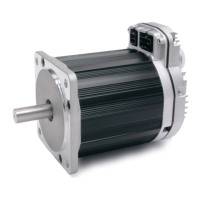
If you need to install a power switch, install an appropriately rated device
on the AC input side of the supply (see figure below). Do not install a
switch on the DC output side. Switching the DC output side—especially
with inexpensive relays—will cause performance degradation over time
due to pitting, corrosion and potential contact welding.
DC
O
UTPUT
F
USE
If you require an external fuse on your power supply’s DC output (to meet
compliance standards for example) it should be installed in line with the
positive leg of the DC output wiring as shown below. Use a maximum 10A,
time delay (slo blo) fuse. Note: Teknic IPC power supplies are not
internally fused on the DC output side.
Power Supply
(IPC-5 shown)
ClearPath Motor
If DC output fuse is required,
install in line with positive (+)
leg of DC output as shown.
If required, install power
switch on AC input side
of supply.
AC Input
DC Output
Fuse @10A Max.
Use slow blow type fuse
Fuse
Power supply switching and fusing detail
S
AFETY
D
ISCONNECT
C
ONTACTOR
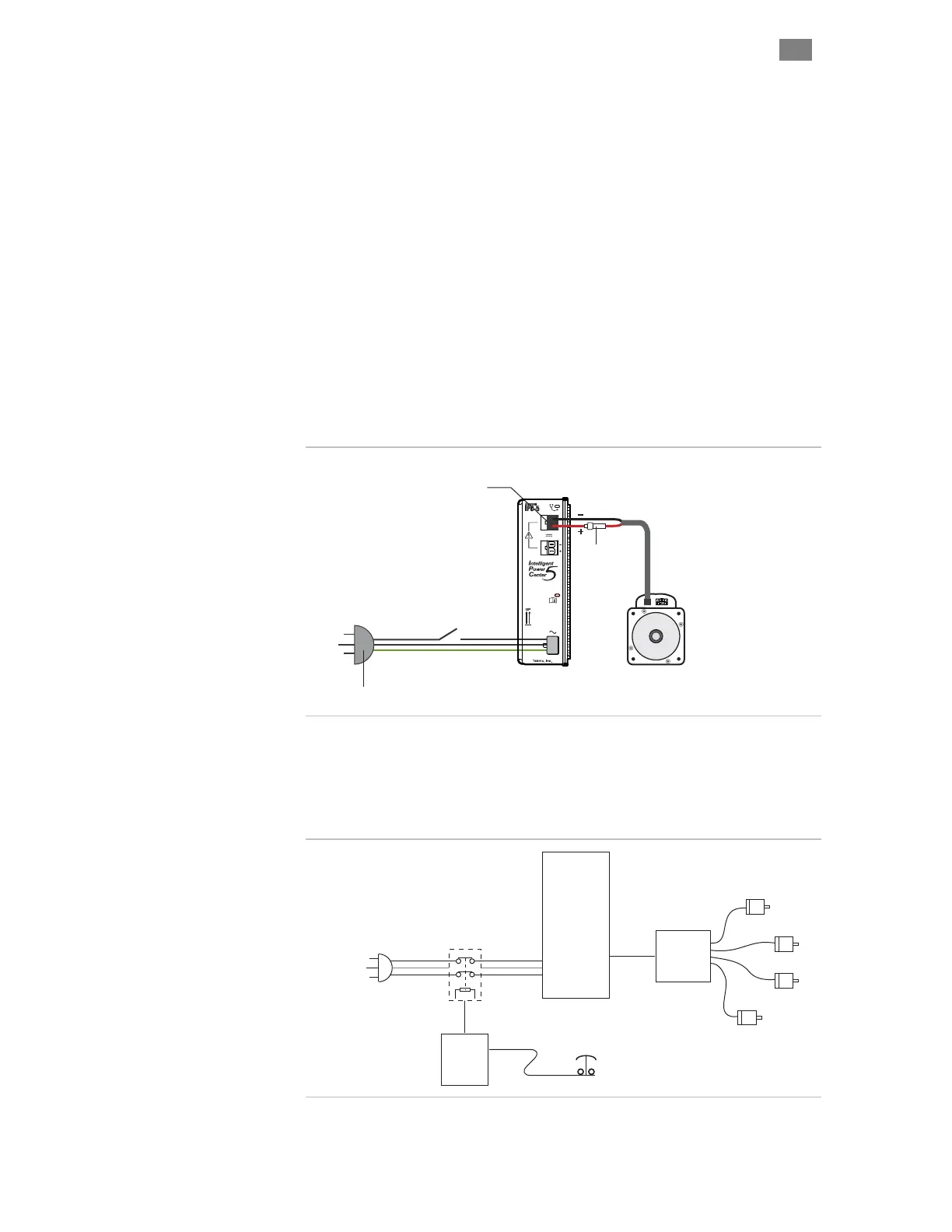
A power disconnect contactor may be placed on the AC input side to
satisfy safety system requirements.
AC Source
110/220VAC
Safety
Control
Power
Supply
Power
Hub
Motors
Contactor
Safety disconnect contactor
 Loading...