C
LEAR
P
ATH
-SC
U
SER
M
ANUAL
R
EV
.
1.36
88
T
EKNIC
,
I
NC
. T
EL
.
(585)
784-7454
A
PPENDIX
A:
M
OTOR
LED
B
LINK
C
ODES
Note: The motor LED periodically blinks off to indicate active
communication between the motor and the host PC. This communication
blinking takes place concurrently with the LED behavior defined in the
table below. See examples below for clarification.
Example 1: A motor that is disabled will exhibit a solid green LED, but
the LED will periodically blink off and back on during communication
with the host PC.
Example 2: An enabled motor will exhibit a rapid green flicker, but the
flicker pattern will be interrupted periodically during communication with
the host PC. (It will look like a rapid flicker mixed with a slow blink.)
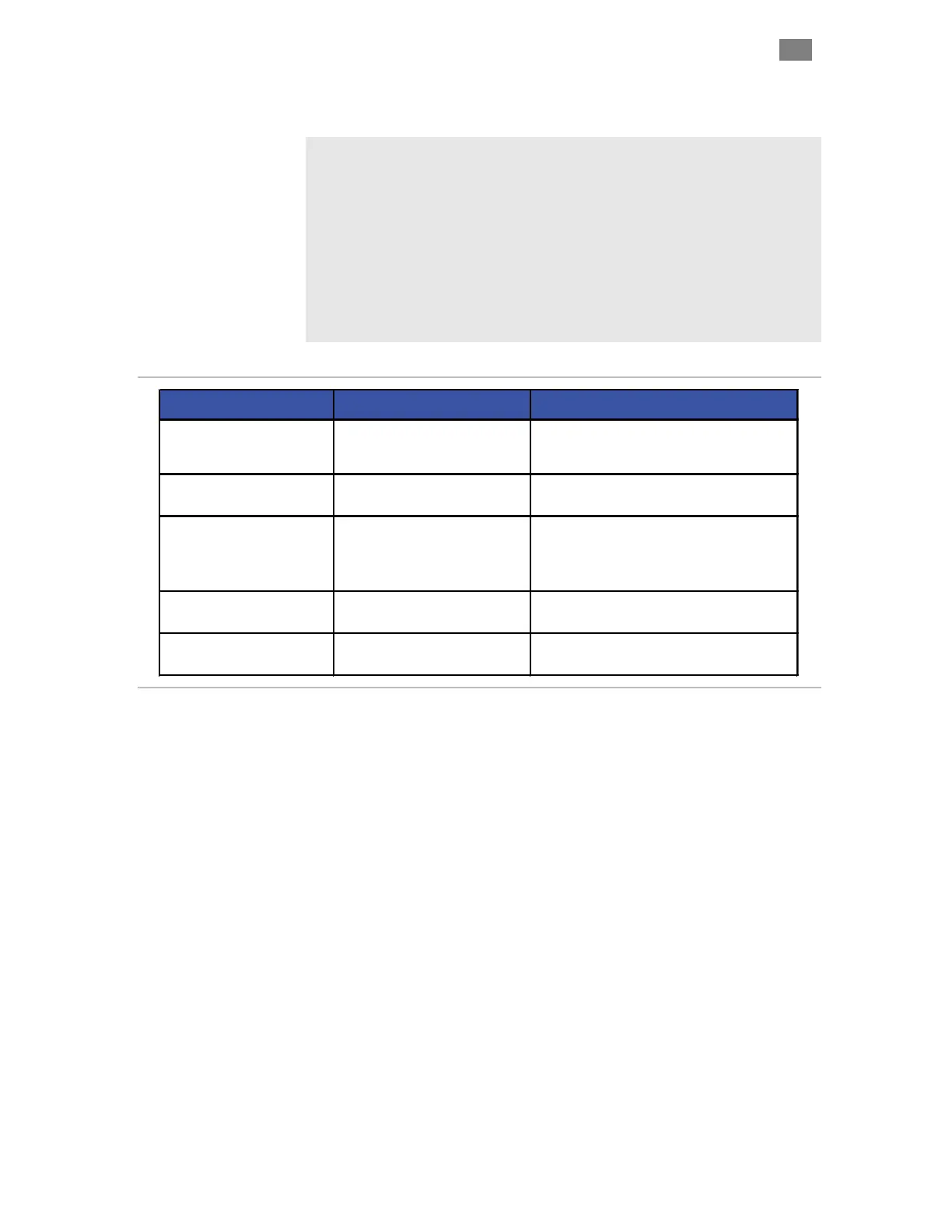
LED Behavior CPSC State Description
Operation normal.
CAUTION:
Motor windings
are energized. Motor can move at any time.
Operation normal. Motor windings are de-
energized.
Query drive through application code for
exception information, or connect to motor via
Diagnostic Port with secondary laptop (running
ClearView).
Motor hardware failure possible. Request RMA
if condition persists.
Off No or low DC bus power
Apply DC bus power to motor. Verify power
supply meets system power requirements.
 Loading...