C
LEAR
P
ATH
-SC
U
SER
M
ANUAL
R
EV
.
1.36
36
T
EKNIC
,
I
NC
. T
EL
.
(585)
784-7454
P
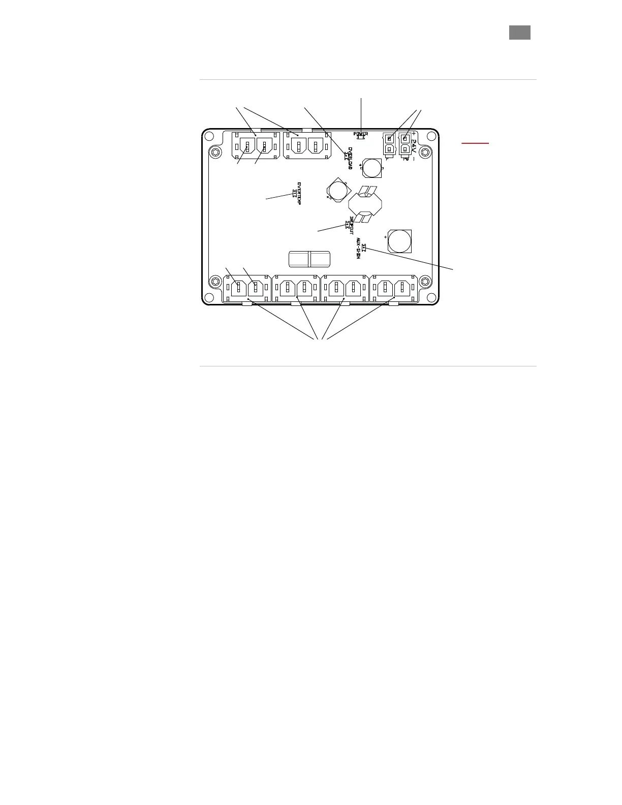
ARTS OF A
POWER4-HUB
24VDC Logic Power *
Input & Passthrough
75V DC Bus
Input & Passthrough
75V Dropout LED
(Aux. power active)
Board Thermal
Shutdown LED
Power Output
To ClearPath Motors
24V Power LED
Output Bus
Overload LED
Aux. (Logic) Power
Overload LED
GND V+
V+ GND
* Note: 24VDC Logic Power
is required for operation.
Parts of a POWER4-HUB
DC Bus Power Input/Passthrough (Qty. 2) - Supply 24-75VDC
power from your DC Bus Supply to either of these connectors (they are
wired in parallel). The other connector can be used to daisy chain bus
power to a second Power Hub if desired, or left unconnected.
DC Bus Power Outputs (Qty. 4) - These four connectors supply bus
power to your CP-SC motors. In addition, if power is dropped, they carry
aux. power to keep maintain motor communication to the host
application. They are fully short-circuit protected.
24VDC Logic Power Input, with Passthrough (Qty. 2) - Supply low
power 24VDC logic power to either of these connectors (they are wired in
parallel). The other connector can be used to daisy chain power to a
second Power Hub.
POWER4-HUB LEDs - There are 5 LED indicators on a Power Hub.
Please refer to the section "Power Hub LEDs" (later this section) for a
complete explanation of what the Power Hub LEDs indicate.
 Loading...