C
LEAR
P
ATH
-SC
U
SER
M
ANUAL
R
EV
.
1.36
42
T
EKNIC
,
I
NC
. T
EL
.
(585)
784-7454
P
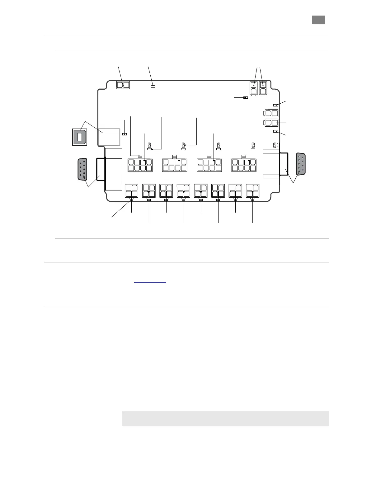
ARTS OF AN
SC4-HUB
CP3
0A 1A
1B 2B 3A
CP0
OPEN
CP2
CP1
0B 2A
3B
+ 24V -
GLOBAL STOP
P4P1 P2 P3
24V
DATA
DB9R-M
DB9R-F
Global Stop
Input
Brake 0 Output
Brake 0 LED
Brake 1 LED
Brake 1 Output
24V Input/Passthrough
Input A
(Axis 3)
Input B
(Axis 3)
Input A
(Axis 0)
Input B
(Axis 0)
ClearPath I/O
(Axis 0)
Input A
(Axis 1)
Input B
(Axis 1)
ClearPath I/O
(Axis 1)
Input A
(Axis 2)
Input B
(Axis 2)
ClearPath I/O
(Axis 2)
ClearPath I/O
(Axis 3)
Global Stop
LED
24V Power
LED
Input
Data
LED
USB Comms
(Type B)
Motor
Placement
LED (x4)
Data
Return
LED (x5)
RS-232 Comms
(DB-9 Female)
Extension
Connector
(DB-9 Male)
Input A LED (x4)
Input B LED (x4)
J0 J1 J2 J3 J5
End of loop
jumper (x5)
SC4-HUB with callouts
SC4-HUB
M
OUNTING
See Appendix B, Mechanical Index, for SC Hub mechanical/mounting
dimensions.
SC4-HUB
O
PERATION
(C
ONNECTOR BY
C
ONNECTOR
)
24VDC
I
NPUT
/
P
ASSTHROUGH
C
ONNECTORS
Connection point for the (required) 24VDC logic power supply. There are
a total of two 2-pin Molex connectors wired in parallel; you can supply
power to either one. The second connector may be used to daisy chain
power to another SC Hub or another 24VDC device if desired.
USB
C
OMMUNICATION
C
ONNECTOR
(USB
C
OMMS
)
This is a standard USB type B connector. Connect SC Hub to your PC
using a readily available cable (USB-B to USB-A).
Important: Never connect a USB and RS-232 connector to the
same SC Hub. This will cause communication errors.
 Loading...