Operating Instructions—
465B Service
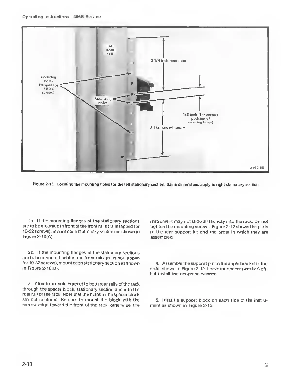
Figure 2-15.
Locating the mounting holes
lor the lelt stationary section. Same dimensions apply
to
right stationary
section
2a
If the mounting flanges
of the stationary
sections
are to
be
mounted
in front of the front
rails (rails tapped for
10-32
screws),
mount each stationary
section as shown
in
Figure 2-l6(A).
2b If the mounting flanges
of the stationary
sections
are to be mounted behind
the front rails
(rails not tapped
for 10-32
screws), mount each stationary
section
as
shown
in
Figure
2-l6(B).
3. Attach an angle
bracket
to
both rear rails
of the rack
through the
spacer block, stationary
section and into the
rear rail of the rack Note
that the holes in the
spacer block
are not centered
Be sure to mount
the block with the
narrow
edge toward the front of
the rack, otherwise, the
instrument
may not slide all the way into the rack. Do not
tighten the mounting
screws. Figure
2-12
shows the parts
in the rear support kit and
the
order
in
which
they are
assembled.
4.
Assemble the support
pin to the angle bracket in
the
order
shown in Figure 2-12.
Leave the spacer (washer) off.
but install
the neoprene washer
5. Install a support block on each
side
of the instru-
ment as shown in Figure
2-13.
@
2-18