Operating Instructions—
465B Service
11.
Adjust the
alignment of
the
stationary sections
according to the procedure outlined in Figure
2-18 (If the
rear alignment is changed, recheck the rear support pins
for correct alignment
)
12 After the tracks operate smoothly, connect the
power cord
to the power source.
13. Push the instrument all the way into the rack and
secure it to the rack with the securi ng screws
and washers
as
shown in Figure
2-17.
NOTE
The securing screws are an important part of the
shock-mounted
installation.
If the front rails
are not
tapped
for
the
10-32 securing screws, other means
must
be provided
for
securing the
instrument
to
the
rack.
ALTERNATIVE REAR MOUNTING
METHODS
Although the following methods provide satisfac-
tory mounting under normal conditions, they do not
provide solid support at the rear of the instrument. If
the
instrument
is
subjected to severe shock or
vibration when mounted using the following
methods, it may be damaged.
An alternative method
of
supporting the rear of the
instrument
is
shown in
Figure
2-19.
The rear support
brackets
supplied with the instrument allow it to be
mounted in a rack
which has
a
spacing between the front
and
rear rails of 11 to 24 inches. Figure
2-
1 9(
A)
illustrates
the mounting method if the
rear rails are
tapped
for
10-32
screws,
and
Figure
2-19(B)
illustrates the mounting
method if the
rear rails
are
not
tapped
for
10-32
screws.
The rear support kit is not used for this
installation.
If the rack does not
have
a rear rail, or if the distance
between the
front and
rear rails is too large, the
instrument
may be mounted without the use of the
slide-out tracks.
Fasten the instrument to the front
rails of
the rack
with
the
securing screws and washers.
This mounting method
should be used only if the instrument will not be
subjected
to shock
or vibration and if
it
is installed in
a
stationary
location.
REMOVING OR INSTALLING THE
INSTRUMENT
After initial installation and
adjustment
of
the slide-out
tracks, the
R465B
can be
removed
or
i nstalled
by
following
the instructions given in Figure
2-17.
No further ad-
justments are
required under normal conditions.
SLIDE-OUT TRACK LUBRICATION
The slide-out tracks
normally require no lubrication
The special finish on the
sliding
surfaces
provides perma-
nent lubrication.
However, if the tracks
do
not slide
smoothly even after
proper adjustment,
a
thin coating of
paraffin rubbed
onto the sliding surfaces may improve
operation.
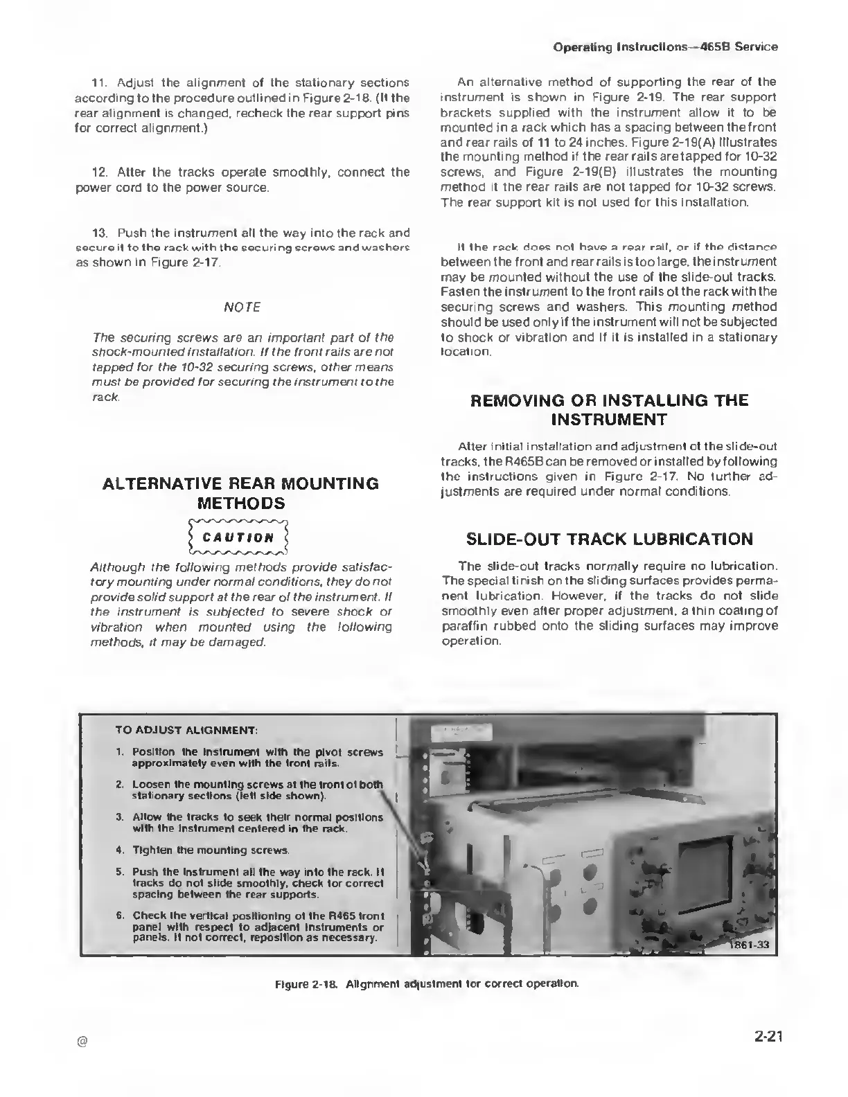
TO ADJUST ALIGNMENT:
1. Position the Instrument with
the pivot screws
approximately even
with the
(ront rails.
2. Loosen the mounting
screws
at
the tront
ol
both
stationary sections (let! side
shown).
3. Allow the tracks
to seek
their
normal positions
with the instrument
centered in the rack.
4. Tighten the mounting
screws.
5. Push the instrument all the way into the rack. It
tracks
do
not
slide smoothly, check for correct
spacing between
the rear
supports.
6. Check
the
vertical positioning ot the R465 front
panel with respect
to adjacent Instruments or
panels. If not correct, reposition
as necessary.
K
11
M
c
f
%\
i'll
i
t
•
I
l
Figure
2-1&
Alignment
adjustment for correct operation.

 Loading...


