Operating
Instructions—465B Service
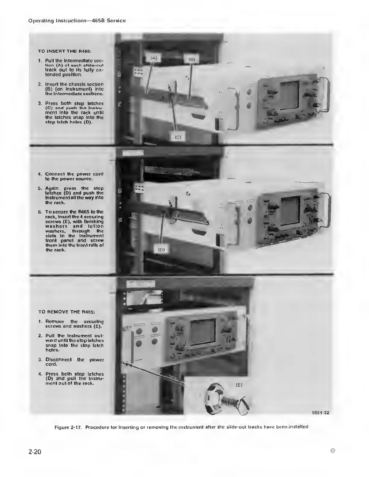
TO INSERT THE
R465:
1. Pull the Intermediate
sec-
tion (A) ot oach dido-out
track out to its fully ex-
tended position.
2. Insert the chassis section
(B) (on instrument)
into
the intermediate sections.
3. Press both stop latches
(C)
and
push tho inctru
men! into
the rack until
the latches
snap into the
stop latch holes
(D).
4.
Connect the power cord
to the power source.
5. Again press
the stop
latches
(D)
and push the
instrument ali the way into
the rack.
6. To
secure the R465 to the
rack, insert the 4 securing
screws (E), with finishing
washers and teflon
washers,
through the
siots in
the instrument
front panel and screw
them into the front
rails of
the rack.
TO REMOVE THE R465:
1.
Remove the securing
screws and washers
(E).
2. Pull the Instrument
out-
ward until the stop latches
snap into the stop latch
holes.
3. Disconnect the
power
cord.
4.
Press
both stop latches
(D) and pull
the
instru-
ment out of the rack.
Figure
2-17.
Procedure for
inserting
or removing
the instrument
after
the
slide-out tracks have been installed
2-20

 Loading...


