Calibration Procedure—465B Service
Performance Check
e.
Move the signal from the
CH
2
OR Y input to the
CH 1 OR X input
connector.
f Set VERT MODE switches for CH 1
display.
g.
Repeat Step
6,
part
d, for
CH 1.
7.
Check BEAM FIND Operation
a. Push in and
hold the BEAM FIND button.
b. CHECK—
A
compressed trace is visible
regardless
of the settings of the:
CH
1
POSITION control.
INTENSITY control, or
Horizontal POSITION control.
c.
Return the Horizontal POSITION control and the
INTENSITY control
to
midrange.
d. While still
holding
in the BEAM
FIND
button,
vertically position the trace to the center horizontal
graticule line.
e. Release the BEAM FIND button.
f. CHECK—Trace
remains
within the graticule area.
g.
Disconnect the test equipment.
8.
Check CH
1
and CH 2 Deflection Factor
a. Connect calibration generator
standard-amplitude
output to the CH 1 input
connector via a 50 O bnc cable.
Use no termination. Set the
generator
for a 20
mV signal
and set the 465B
AC-GND-DC switches to DC.
b.
CHECK—CH 1 deflection factor
is within the limits
given
in Table
4-2.
c Set the VERT MODE switches to
display
CH 2.
and
move the
signal from CH 1 OR X input to the CH 2 OR Y
input connector.
d.
CHECK—CH
2
deflection factor is
within the limits
given in Table
4-2.
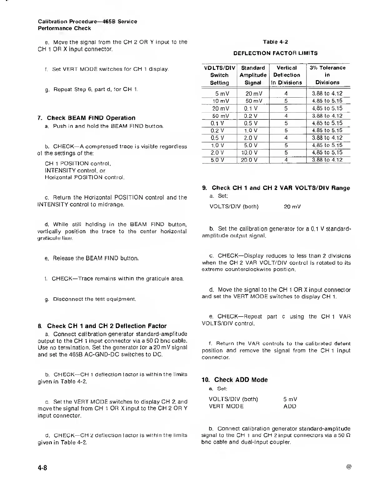
Table
4-2
DEFLECTION FACTOR LIMITS
VOLTS/DIV
|
Standard Vertical
3% Tolerance
Switch
Amplitude
i
Deflection in
Setting
Signal in Divisions Divisions
5
mV 20 mV 4 3.88
to 4.12
10 mV 50 mV 5
4.85 to 5.15
20 mV 0.1 V 5
4.85 to 5.15
50
mV 0.2 V 4 3.88
to 4.12
0.1 V
0.5 V 5 4.85
to
5.15
0.2 V 1.0 V 5
4.85 to 5.15
0.5
V 2.0 V 4 3.88
to 4.12
1.0 V
5.0
V 5
4.85 to 5.15
2.0 V
10.0 V 5 4.85 to
5.15
5.0
V
20 0
V 4 3 88 to
4.12
9.
Check CH 1 and CH 2 VAR VOLTS/DIV Range
a. Set:
VOLTS/DIV
(both) 20 mV
b.
Set the calibration generator
for a 0.1 V standard-
amplitude
output signal.
c.
CHECK—Display reduces
to less than 2 divisions
when
the CH 2 VAR VOLT/DIV control is rotated to its
extreme counterclockwise
position.
d.
Move
the signal to the CH 1 OR X input connector
and set the
VERT
MODE switches to display CH 1.
e, CHECK—Repeat
part c using the CH 1 VAR
VOLTS/DIV control.
f. Return the VAR
controls to the calibrated detent
position and remove the signal from
the
CH
1
input
connector.
10.
Check
ADD Mode
a. Set:
VOLTS/DIV
(both) 5 mV
VERT MODE
ADD
b. Connect calibration generator standard-amplitude
signal
to the
CH
i and
CH
2 input connectors via a 50 Q
bnc cable and dual-input coupler.
4-8

 Loading...


