Performance tests
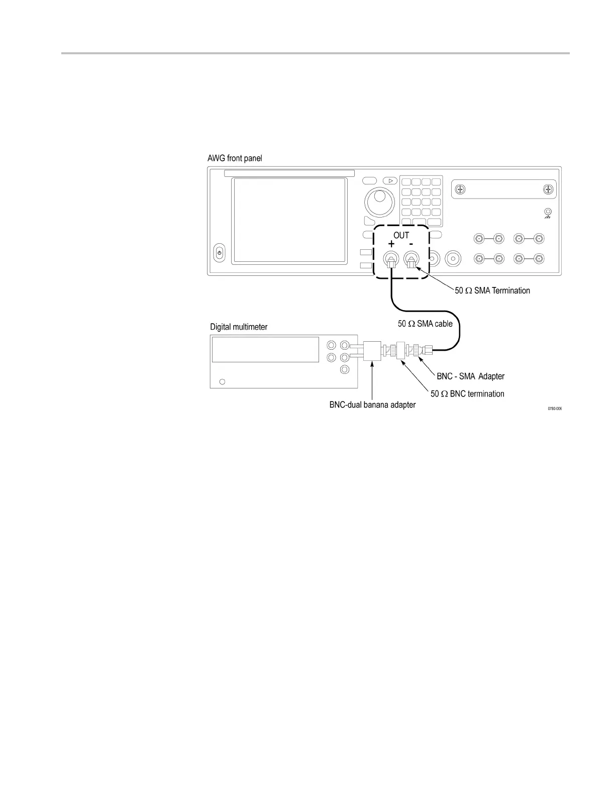
3. Use the 50 Ω SMA c
able to connect the CH 1 + connector on the instrument
to the HI and LO inputs on the digital multimeter.
4. Use the 50 Ω SMA
termination to terminate the CH 1 – connector on the
instrument.
Figure 2-14: Equipment connection for checking the analog amplitude accuracy
5. Press the Home button on the instrument, o r click the Home tab on the display.
6. Clic
ktheReset to default setup button in the Setup Shortcuts tab.
7. On the instrument, load the PV_DC_Plus.wfmx waveform as an output
wave
form:
a. Select Open Waveform.
b. In the dialog box, navigate to the C:\Program
Files\Tektronix\AWG70000\Samples\PV folder, and then
se
lect the PV_DC_Plus.wfmx file. The Waveform List window appears.
c. In the window, drag and drop the PV_DC_Plus.wfmx waveform on the
w
ork space.
8. From the Setup tab, click the Channel 1 button.
9. Set the amplitude of the i nstrument as shown in the first row of the table:
AWG70000A Series and AWGSYNC01 Technical Reference 2–25
 Loading...


