Performance tests
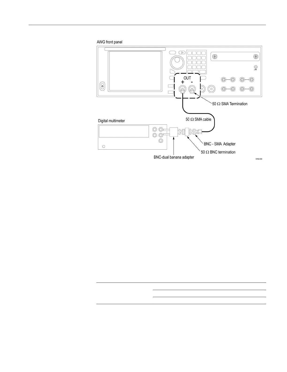
Figure 2-16: Equipment connection for checking the analog amplitude accuracy
5. Press the Home button on the instrument, o r click the Home tab on the display.
6. Click the Reset to default setup button in the toolbar.
7. On the instrument, load the PV_DC_Plus.wfmx waveform as an output
waveform:
a. Select Open Waveform.
b. In the dialog box, navigate to the C:\Program
Files\Tektronix\AWG70000\Samples\PV folder, and then
select the PV_DC_Plus.wfmx file. The Waveform List window appears.
c. In the window, drag and drop the PV_DC_Plus.wfmx waveform on the
work space.
8. Set the amplitude of the i nstrument as shown in the first row of the table:
Table 2-6: AC analog amplitude accuracy
Model Amplitude settings Accuracy lim its
250 mV
p-p
244 mV to 256 mV
375 mV
p-p
367 mV to 383 mV
AWG70000A series
500 mV
p-p
489 mV to 511 mV
9. Press the Ch 1 Enable button on the instrument to enable the channel 1 output.
10. Press the Play button on the instrument to output the signal.
AWG70000A Series and AWGSYNC01 Technical Reference 2–29
 Loading...


