Troubleshooting
CSA7404B, TDS7704B, TDS7404B, TDS7254B & TDS7154B Service Manual
6-69
If the mains power switch is on and the instrument is not on, (power supply is in
standby mode), a red light (see Figure 6--44 for its location) is visible through
the right side of the instrument. If the instrument is on, the red light is off.
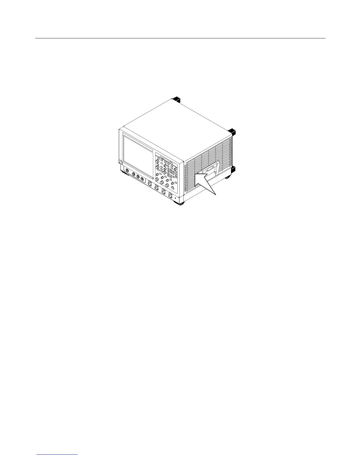
Mains power-on and over current LEDs are
near the center of the power supply. A red
glow from them is visible while looking
through the side of Instrument
Figure 6- 44: Location of power-on and over current LEDs
If the instrument thinks power is on, a red light (see Figure 6--44) means that
there is an over current condition.
If the on/standby pin (pin C1 of P201 on the rear power distribution board or pin
B162 on the bridge board) is low, the instrument thinks power is on.
Remove boards one at a time to locate a fault (the display, floppy, acquisition
board, front [analog supply to acquisition board] and power distribution board,
and the MicroATX and the bridge boards). If you remove the MicroATX board,
you must also remove the bridge board. The PPC board and the rear power
distribution board are required for power to come up.
If removing the boards did not find the problem, replace the power supply.
To check the power supply voltages, power on the instrument and connect the
reference lead of a digital voltmeter to chassis ground, such as the top of the
power supply.
Attach a 0.025 inch square pin to the probe tip of the other lead and insert it into
a pin on one of the connectors. The pins that should be carrying voltages are
listed in Table 6--5. The location of the J1 and J2 connectors is shown in
Figure 6--45 on page 6-- 70.
Isolating to a Board if
Power Will Not Come Up
Checking the Power
Supply Voltages

 Loading...


