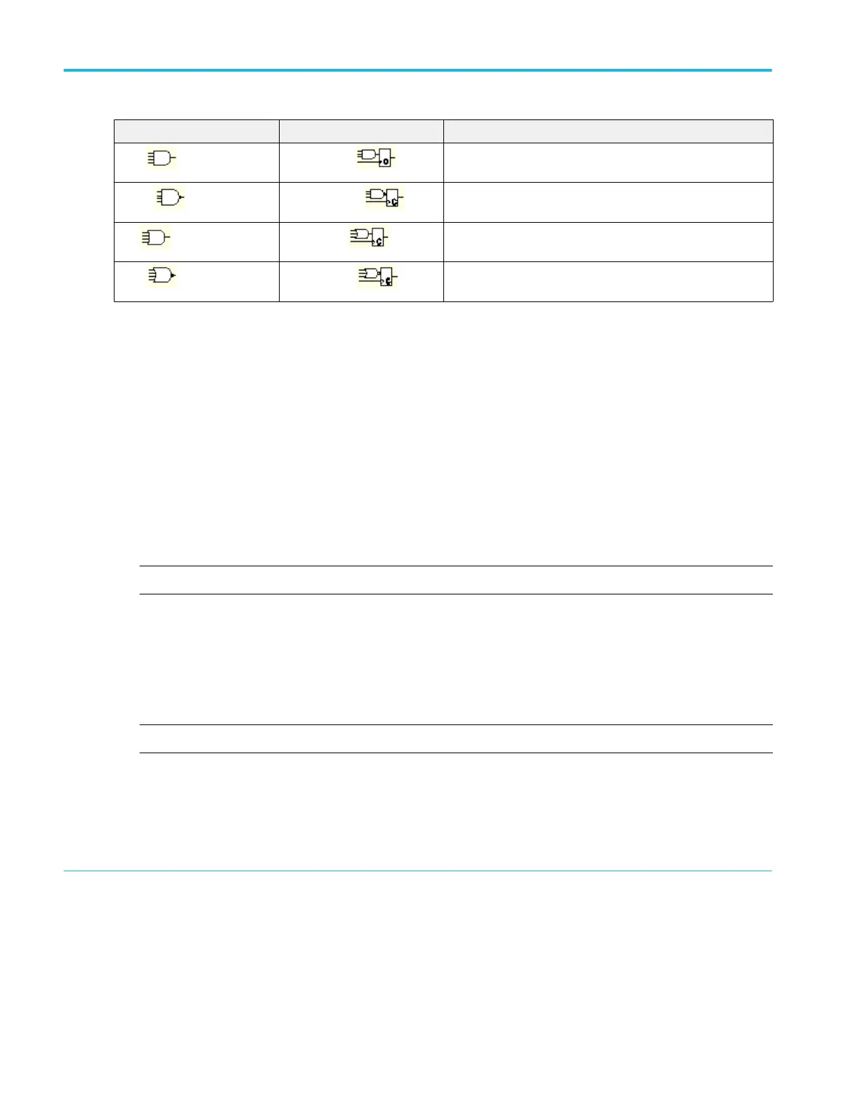
Pattern State Definition
7
,
8
AND
Clocked AND
If all the preconditions selected for the logic inputs
9
are TRUE,
then the instrument triggers.
NAND Clocked NAND
If not all of the preconditions selected for the logic inputs
10
are
TRUE, then the instrument triggers.
OR
Clocked OR
If any of the preconditions selected for the logic inputs
11
are
TRUE, then the instrument triggers.
NOR
Clocked NOR
If none of the preconditions selected for the logic inputs
12
are
TRUE, then the instrument triggers.
Trigger on a logic state
Use the following procedure to trigger the instrument when all of the logic inputs to the selected logic function cause the function
to be True or False when the clock (channel 4) input changes state.
1. Push the front-panel Advanced button.
2. In the Trigger control window, Open the A Event tab.
3. Select State from the Trigger Type drop-down list.
4. Select a value from the Input Threshold drop-down list for each data channel. The channel inputs combine to form a logic
pattern. Each channel can have a value of high (H), low (L), or "don't care" (X). A value is considered high if the channel
input voltage is greater than the specified threshold voltage. A value is considered low if the channel input voltage is less
than the specified threshold voltage. Use the "don't care" selection for any channels that will not be used as part of the
pattern.
NOTE. Channels 1, 2, and 3 represent the data inputs. Channel 4 should be connected to the clock signal.
5. Select either the POS (rising) or NEG (falling) edge for the Clock Channel (Channel 4).
6. To set the Input Threshold voltages, click one of the Threshold Presets buttons to define the level type. If you selected
USER, click in the Ch <1–4> entry boxes, and then use the multipurpose knobs or pop-up keypad to set each threshold.
7. Select the Pattern Type Boolean logic function for the combination of input channels. The instrument will trigger on a clock
edge when the input waveforms match the specified logic pattern.
NOTE. See Pattern Triggers for definitions of the logic functions for pattern triggers.
7
For state triggers, the definition must be met at the time the clock input changes state
8
The definitions given here are correct for the Goes TRUE setting in the Trigger When menu. If that menu is set to Goes False, swap the definition for AND with that for
NAND and for OR with NOR for both pattern and state types.
9
The logic inputs are channels 1, 2, 3, and 4 when using Pattern triggers. For State triggers, channel 4 becomes the clock input, leaving the remaining channels as logic
inputs.
10
The logic inputs are channels 1, 2, 3, and 4 when using Pattern triggers. For State triggers, channel 4 becomes the clock input, leaving the remaining channels as logic
inputs.
11
The logic inputs are channels 1, 2, 3, and 4 when using Pattern triggers. For State triggers, channel 4 becomes the clock input, leaving the remaining channels as logic
inputs.
12
The logic inputs are channels 1, 2, 3, and 4 when using Pattern triggers. For State triggers, channel 4 becomes the clock input, leaving the remaining channels as logic
inputs.
How to ?
630 DPO70000SX, MSO/DPO70000DX, MSO/DPO70000C, DPO7000C, and MSO/DPO5000B Series
 Loading...


