Calibration-PS
501
0
Performance Check Procedure
c.
Press the following buttons in the order listed:
SUPPLY SELECT
POS
5
ENTER
CURRENT
4
6
ENTER
d. Turn the OUTPUT
ON.
e. Note the dvrn reading
(4.990
V to
5.01 0
V).
f. Turn the OUTPUT OFF.
g.
Connect the
5
52
resistor from the front panel POSITIVE
terminal to the front panel common terminal.
h. Turn the OUTPUT
ON.
i.
CHECK-the dvrn for a reading.of
=GI0
mV from the
reading noted in step e.
To prevent resistor overheating do not leave the resis-
tor connected for longer than necessary to make the
check.
Repeat steps a through i for the NEGATIVE supply.
Substitute the word NEGATIVE for POSlTlVE in these
steps. All tolerances and voltages are identical except
for the sign change.
To verify the rear interface output load effect see Fig.
5-
1.
All entered values are identical.
m. Change the front-rear switch on the rear panel of the
instrument to rear.
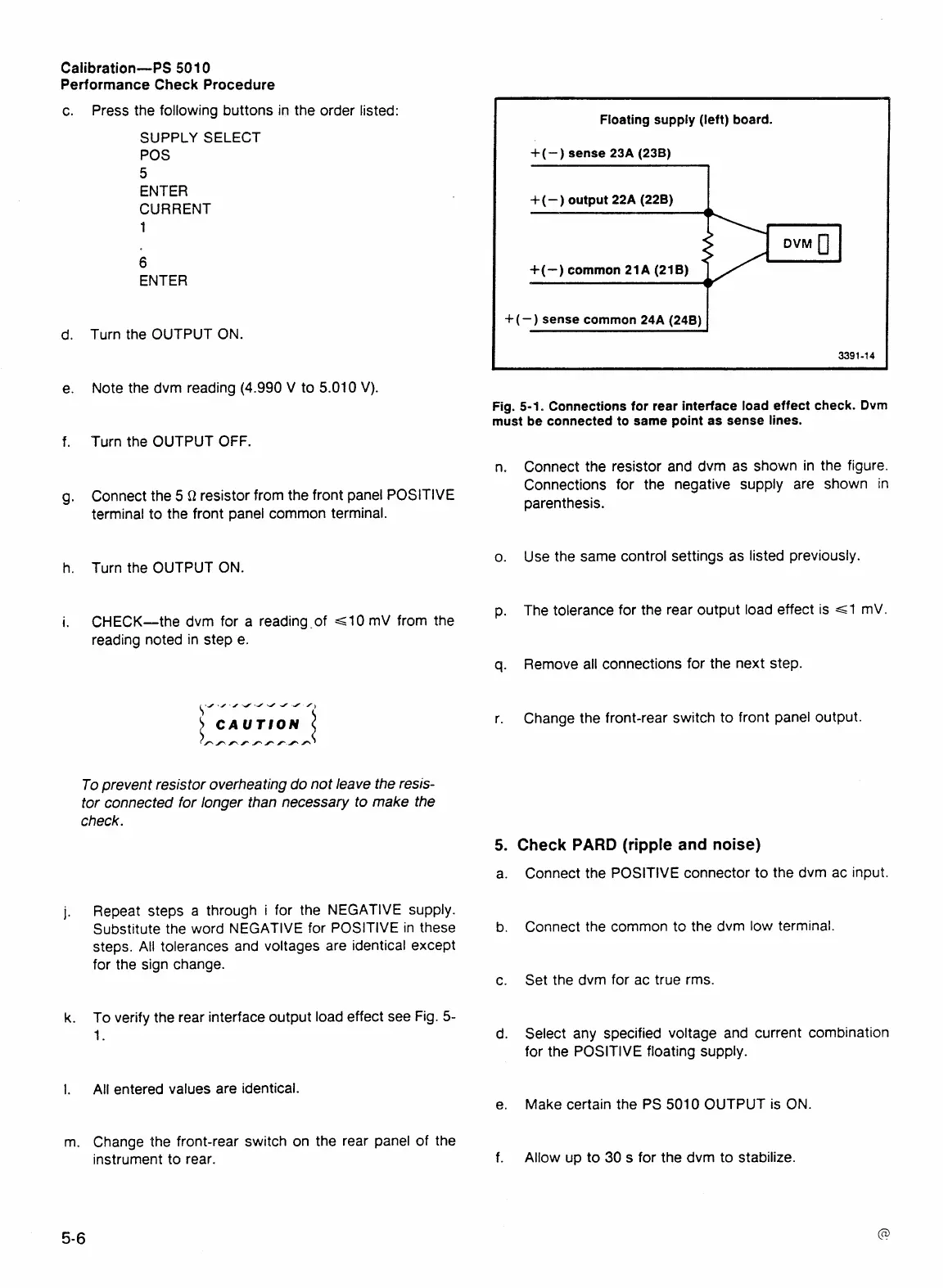
Floating supply (left) board.
+
(
-
)
sense
23A (238)
I
+
(
-
)
output
22A
(228)
+(-)
common
21A (218)
7-
+
(-)
sense common
24A (2481
1
Fig.
5-1.
Connections for rear interface load effect check.
Dvm
must be connected to same point as sense lines.
n.
Connect the resistor and dvrn as shown in the figure.
Connections for the negative supply
are shown
in
parenthesis.
o.
Use the same control settings as listed previously.
p.
The tolerance for the rear output load effect is
=GI
mV.
q.
Remove all connections for the next step.
r.
Change the front-rear switch to front panel output.
5.
Check
PARD
(ripple
and noise)
a.
Connect the POSITIVE connector to the dvrn ac input.
b.
Connect the common to the dvrn low terminal.
c. Set the dvrn for ac true rms.
d. Select any specified voltage and current combination
for the POSITIVE floating supply.
e.
Make certain the PS
SO1 0
OUTPUT is ON.
f.
Allow up to
30
s
for the dvrn to stabilize.
 Loading...


