Calibration-PS
50
1
0
Performance Check Procedure
g.
CHECK-that the dvm display reads
=GI
mV rms.
e. Set the front panel pushbuttons for a
5
V
1.6
A
output
voltage.
h. Connect the oscilloscope vertical input to the front
panel POSITIVE and common terminals through a
1X
f.
Alternately open and close the switch in series with the
probe.
5
11
load.
Ac couple the oscilloscope input. Set the bandwidth
limit to
20
MHz.
CHECK-that
'
the oscilloscope reads
~10
mV peak-
to-peak.
Repeat this check for the NEGATIVE floating supply.
The specifications are identical.
Remove these connections for the next step.
6.
Check Load Transient Recovery
a.
Make certain the OUTPUT is OFF.
Connect the test fixture shown in Fig. 5-2 to the front
panel common and POSITIVE output connectors.
'/
2A
switch
Fig.
5-2.
Test fixture for load transient recovery.
c.
Connect the oscilloscope to the front panel POSITIVE
and common connectors.
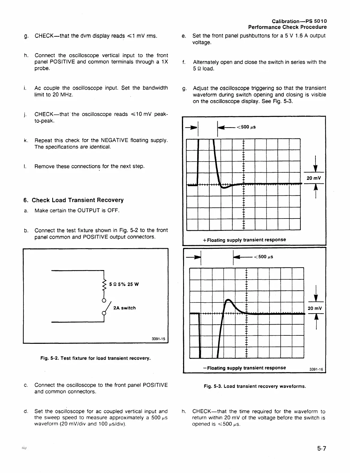
g. Adjust the oscilloscope triggering so that the transient
waveform during switch opening and closing is visible
on the oscilloscope display.
see Fig. 5-3.
4-
t
500
jls
+Floating supply transient response
-Floating supply transient response
3391-16
Fig.
5-3.
Load transient recovery waveforms.
d. Set the oscilloscope for ac coupled vertical input and
h.
CHECK-that the time required for the waveform to
the sweep speed to measure approximately a 500 ps
return within
20
mV of the voltage before the switch is
waveform
(20
mV/div and 100 psldiv).
opened is ~500
ps.
 Loading...


