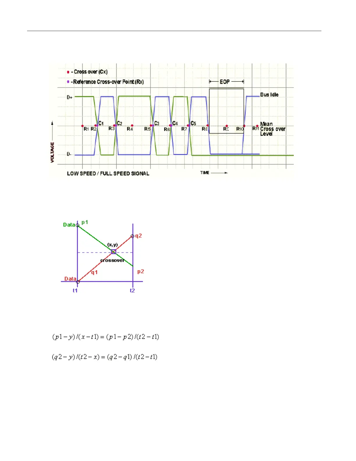
Reference Cross-Over Voltage for Low Speed and Full Speed Signals
In the next figure, C1, C2, C3, C4 and C5 are called Cross-Over Points and R1, R2, R3, R4, R5, R 6 and R7
are called Reference points.
The following figure explains the interpolation technique used to find the actual cross over where p1 and
p2 are the adjacent data points after q2:
The intersection of the four voltage points p1, p2, q1, and q2 gives the Cross-Over point for Voltage level
(y) and time (x). x and y coordinates are obtained by solving the following two equations:
Where:
p1, p2, q1, and q2 are the consecutive data points of a single-ended signal.
x and y are the Cross-Over coordinates x and y that is given by the intersection of p1, p2, q1, and q2.
176 TDSUSB2 Universal Serial Bus Measurements Package
 Loading...


