Operating Basics Droop Mea surement
Droop Measurement
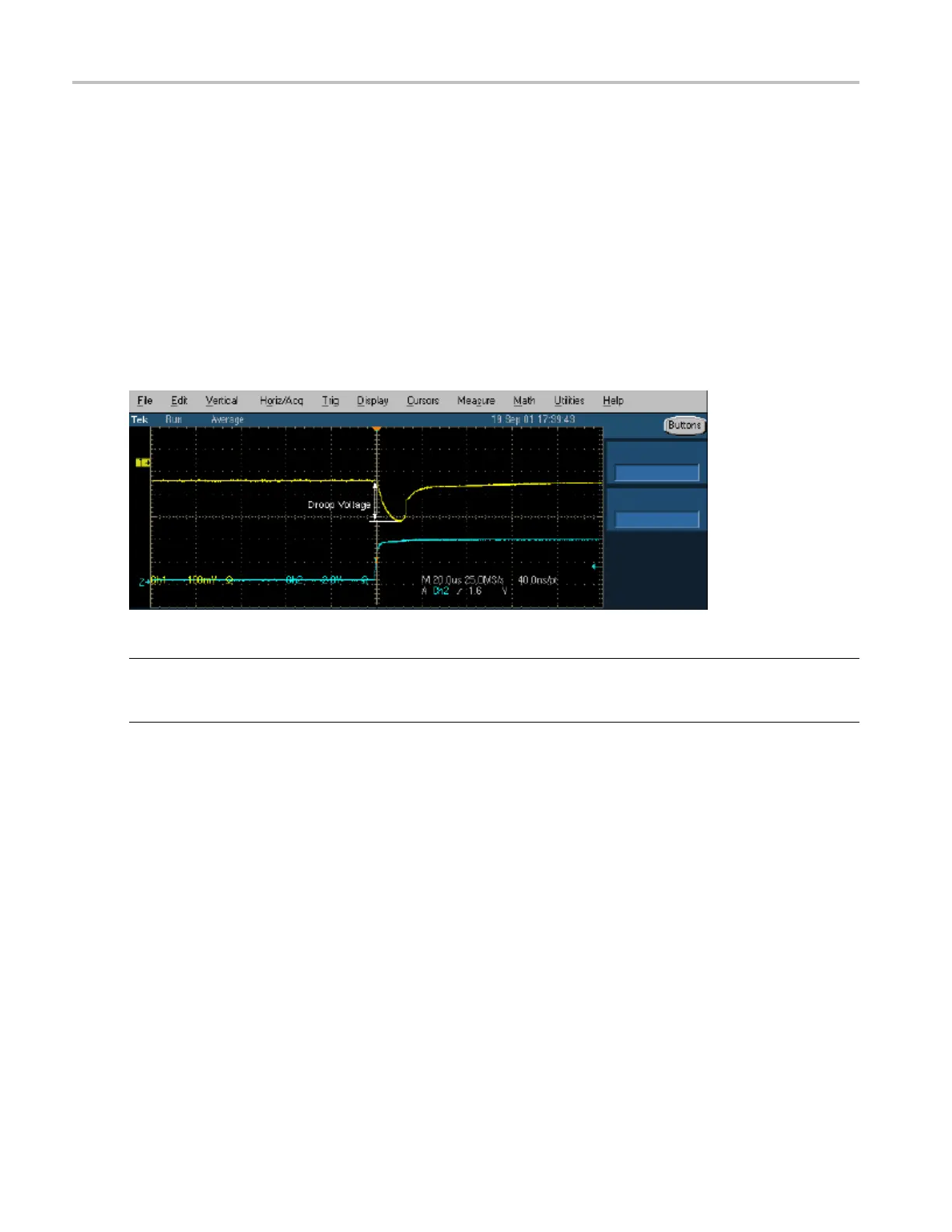
The Droop voltage is the difference in the V
BUS
voltage when you apply a no load condition and a 100 mA
load to the port under test (all other ports are fully loaded).
The Droop test evaluates the worst case droop by alternately applying a droop load and no load to the port
under test while all other ports are supplying the maximum load possible. All the V
BUS
measurements
are relativ
e to local ground.
The TDSUSB2 application automatically sets up the oscilloscope for the specified test configuration.
When you st
art the application, it acquires the signal, and provides the V
DROOP
measurement, and displays
PASS or FAIL.
NOTE. The TDSUSB2 application helps to report the Drop test. You can do this by enabling an option in
the Fi
le> Preferences> Advanced menu. You can enter the multimeter reading for the Drop test in the
TDSUSB2 application during report generation for a consolidated report.
Rec
eiver Sensitivity Measurement
To i
mprove the performance of the application in a noisy environment, the USB2.0 high speed device
should respond to IN tokens with NAKs when the signaling level is at or above the specified level.
Th
e Receiver Sensitivity test requires a high-speed data simulator, such as the Tektronix DTG5334,
DTG5274, or DTG5078; or the AWG5000 series (AWG5002) or AWG7000 series generators, to transmit
IN tokens of varying amplitude. The test requires the unit under test to be placed in the Test_SE0_NAK
mode. The host is then replaced by the data simulator to continue to transmit IN tokens. The signaling
amplitude is presented to the device under test at a level at or above 150 mV. At these levels, the unit
under test must not be in the squelched mode, responding to IN packets with NAKs. The amplitude of
the signals from data senerator varies less than 100 mV. The unit under test must be squelched and not
respond to IN tokens with NAKs.
34 TDSUSB2 Universal Serial Bus Measurements Package
 Loading...


