Operating Basics Chirp Measurement
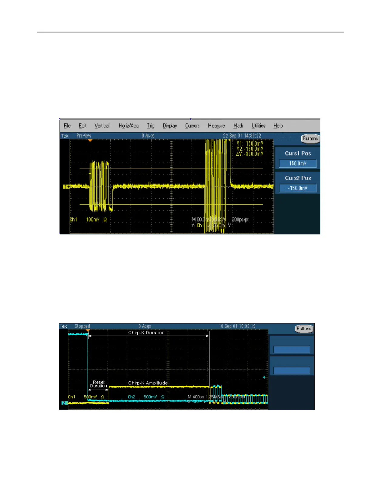
This tests the receiver capability of high speed units (device) to respond to the particular data pattern
generated by the USB2.0 data simulator. The unit under test responds to the data pattern level above the
squelch level
(>150 mV) and should not respond when the data patte rn level is below the squelch level
(<100 mV).
The TDSUSB2 a
pplication provides the procedural steps to perform this measurement. It also provides
Digital signal generator pattern files (AWG5k-HS-USB.zip and DTG_setup.zip are available for
download from www.tektronix.com). Pattern files for other Tektronix data simulators are available from
www.tektronix.com.
Chirp Measurement
To perform a Chirp test, connect the unit under test and the single-ended probes to acquire data. You can
measure the Data for Chirp K amplitude, Chirp K duration, and Reset duration. You need to manually
verify that there are three K–J pairs in less than 500 µs.
TDSUSB2 Universal Serial Bus Measurements Package 35
 Loading...


