Reference Full Speed Upstream Signal Quality Setup
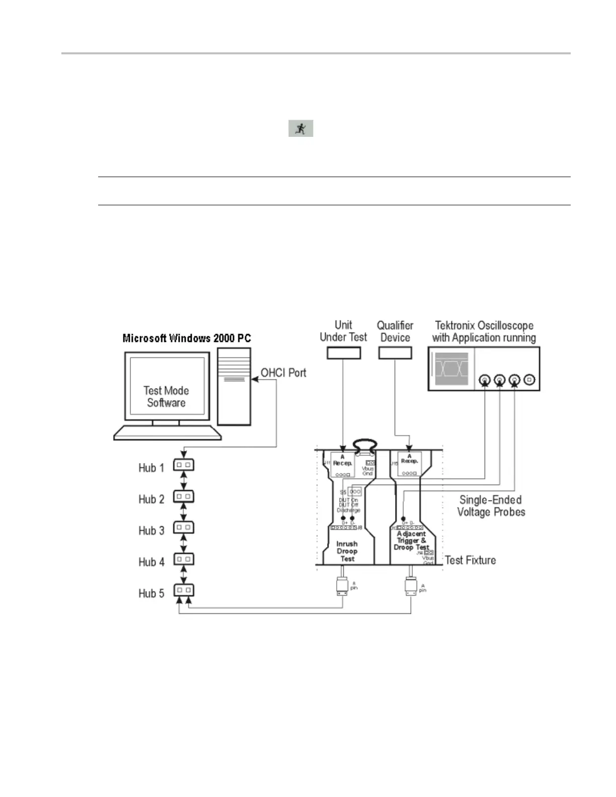
6. Use the connectors to connect the A pin dongle from the Adjacent Trigger and Droop section of
the test fixture to one port of Hub 5. Use the A pin dongle from the Inrush Droop section of the
test fixture to
another port of Hub 5.
7. Select the measurement and select the
command button to run the application.
8. Select OK after acquiring a waveform. Verify that it is a correct waveform.
NOTE. Use the standard USB cables to connect between the hubs. Keep the Discharge switch in the
Inrush Droop section in the ON position.
If the signal is clipped, follow these steps to increase the vertical scale:
1. In the oscilloscope menu, select Vertical>Vertical Setup to display the Channel screen.
2. In the Scale fi eld, increas e the vertical scale values until the waveform is completely displayed on
screen.
TDSUSB2 Universal Serial Bus Measurements Package 195
 Loading...


