Reference Chirp Test Equipment Setup
1. Set the S6 switch to the Init position.
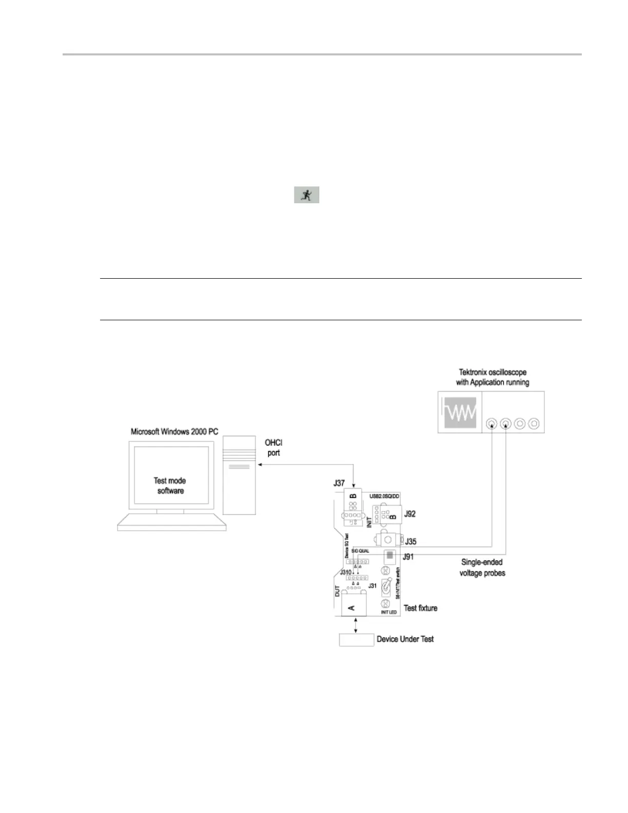
2. Use a standard USB cable with an A plug on one end and B plug on the other end. Connect one end
of the cable to the B socket on the Init port of Device SQ section and the o ther end to the host port
A socket.
3. Connect the A receptacle from the Device SQ test port to the unit under test (device).
4. Connect the single-ended probes of the oscilloscope to the D+ and D– pins.
5. Select the measurement and select the
command button to run the application.
6. Disconnect and connect the unit under test (device) to the port and observe the chirp signal on the
oscilloscope.
7. Select OK after acquiring a waveform. Verify that it is a correct waveform.
NOTE. To avoid false triggering for the chirp signals while operating the test fixture, it is recommended
that you place the switch in the Init position and connect the unit under test. This disables the switch
bounce to the trigger.
TDSUSB2 Universal Serial Bus Measurements Package 197
 Loading...


