MIDSECTION
5-13
1-/ 2-Cylinder
Twist Handle and Linkage Inspection
1. Check all components for wear or cracks.
2. Lubricate aII moving surfaces.
Twist Handle and Linkage Assembly
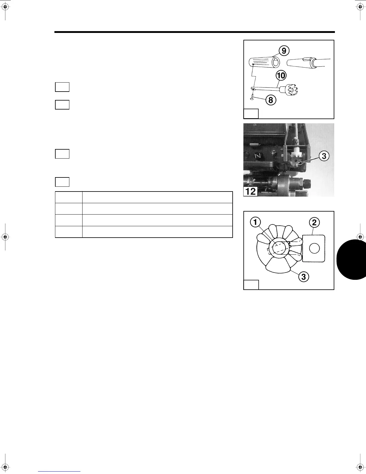
1. lnstall throttle shaft A
(10)
after applying grease.
2. lnstall grip on handle A and insert the handle grip
(9)
and
mounting screw
(8)
.
3. lnstall Throttle Shaft B Assembly in the lower motor cover,
installing the tip of inner throttle shaft in the proper orientation for
the link rod.
4. lnstall the universal pinion
(3)
after coating with grease.
Maintain the relationship between inner throttle shaft and the
universal pinion, and inner throttle shaft and the collar as shown.
5. Assemble handle and assembly to the steering bracket.
6. Tighten the handle friction bolt so that the handle does not drop
from the vertical position.
7. lnstall the throttle shaft supports.
Item Description
1. Spring Pin
2. Throttle Shaft B
3. Universal Pinion
11
11
12
13
T2010
11
T2009
 Loading...