SECTION 7
7-26
1-/ 2-Cylinder
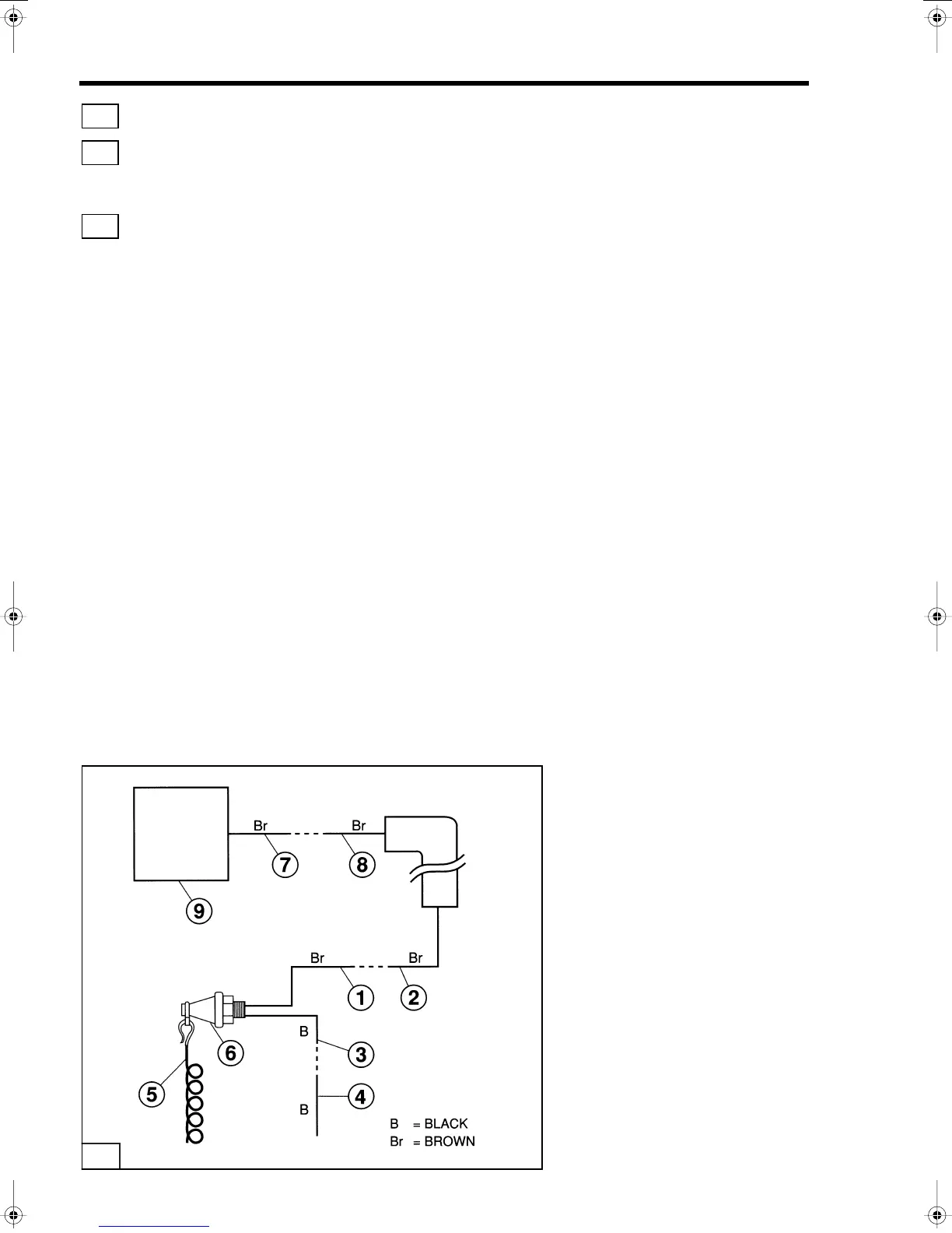
6. Disconnect CD Unit
(8)
terminals
(5)
and
(6)
.
7. Connect one meter lead to terminal
(6)
and the other to
terminal
(2)
and check continuity. If the meter does not show
continuity, replace the cable.
8. Connect one meter lead to terminal
(6)
and the other to a
clean engine ground. If the meter shows continuity, replace
the cable.
9. Reconnect aIl wires and return to Test 2 - Stop Circuit Test flow
chart.
Test 2b - Stop Circuit Emergency Stop Switch Test
This test is used to determine whether the emergency stop switch
and connecting wiring are functioning normally.
NOTIE
Make sure aIl electrical terminals are connected
during this test except those that are noted in the
test pro cedure.
Check for continuity between chassis ground and
the ground connection for the magneto plate, CD
Unit, and ignition coils before conducting the
following procedure.
All continuity tests must be conducted with negative
lead from battery disconnected or you may damage
the meter.
5
5
5
T1476
5
 Loading...