ELECTRICAL SYSTEM
7-7
1-/ 2-Cylinder
ELECTRICAL SERVICING
STANDARDS
Electrical Connectors
When you replace electrical components or perform diagnostic tests,
you must disconnect electrical connectors in many instances.
The following discussion will help you recognize connectors in
electrical drawings and show you how to disconnect and connect
them.
EIectrical Connector Drawings
ln most of the electrical drawings in this section, the physical shape
of electrical connectors has been eliminated to clarify testing
procedures.
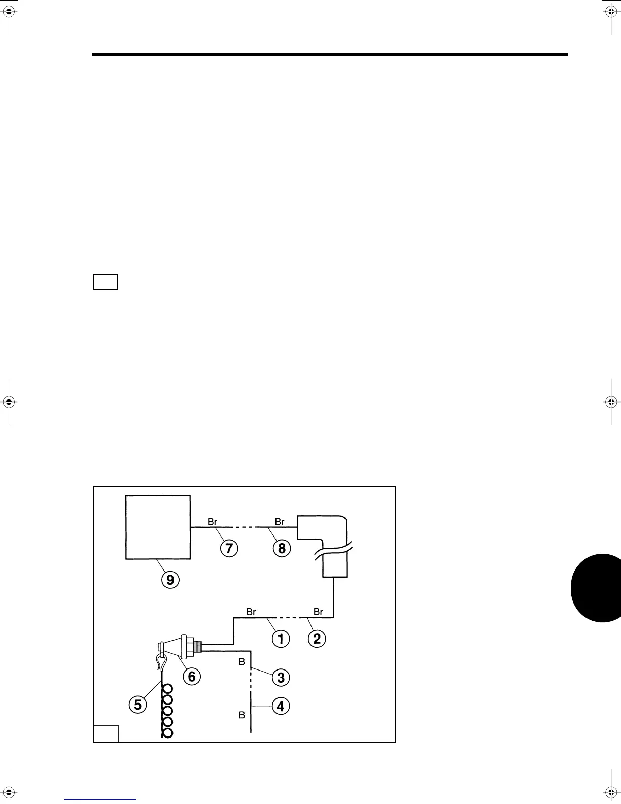
A typical electrical drawing illustrates several connectors. Items
(1)
,
(2)
,
(3)
,
(4)
,
(7)
and
(8)
are terminals that are located inside
of electrical connectors. The dashed line between two terminals [e.g.,
between terminal
(7)
and
(8)
] means that they are a part of the same
connector but have been disconnected for testing.
Note that Terminal
(7)
is directly connected to the CD Unit
(9)
(no
connectors between the terminal and CD Unit). When you disconnect
an electrical connector to test a component, it is very important that
you disconnect the FIRST CONNECTOR. Terminals
(1)
,
(3)
and
(7)
are
examples of how the first connector is illustrated.
1
T1476
1
 Loading...