SECTION 7
7-8
1-/ 2-Cylinder
Special cases are the connectors used to test components
located on the coil plate assembly. For testing purposes, the
first connector is located at the far end of the cable (away from the coil
plate assembly).
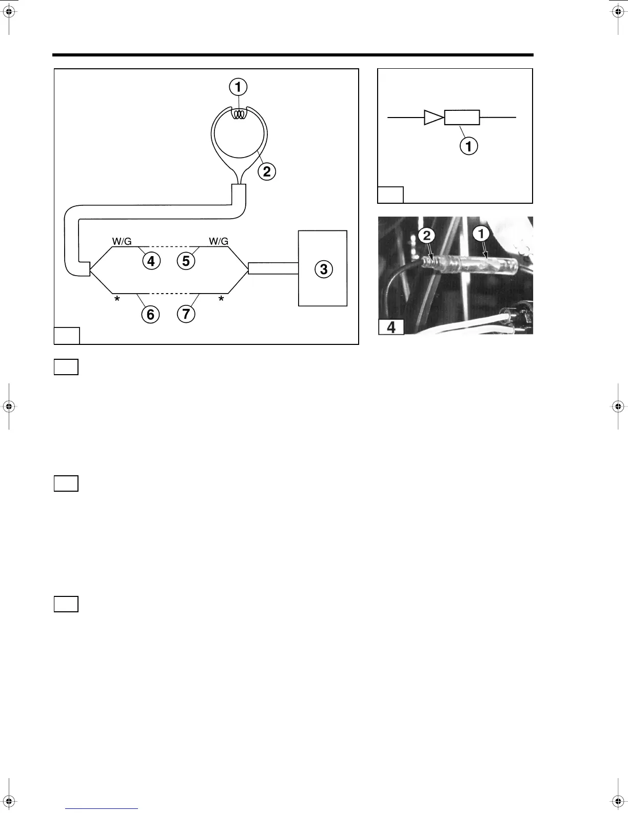
Bullet Connectors
NOTE
Bullet connectors
(1)
are shown like this in electrical
drawings.
Disconnecting Bullet Connectors
1. Carefully examine the connector to determine which end is removable
and which end is fixed. Typically the insulation surrounding the
removable end is tapered so it fits inside of the insulation for the fixed
end.
2. Grasp the fixed end
(1)
of the connector and carefuIIy pull
the removable end
(2)
straight out without twisting or
bending it.
NOTE
Never twist or bend bullet connectors or damage to
the connectors will occur. Always PULL these
connectors apart.
T1479
2
2
3
4
T1477
3
T1465
 Loading...