Assembly
STEP
2:
Install
the
Handlebars
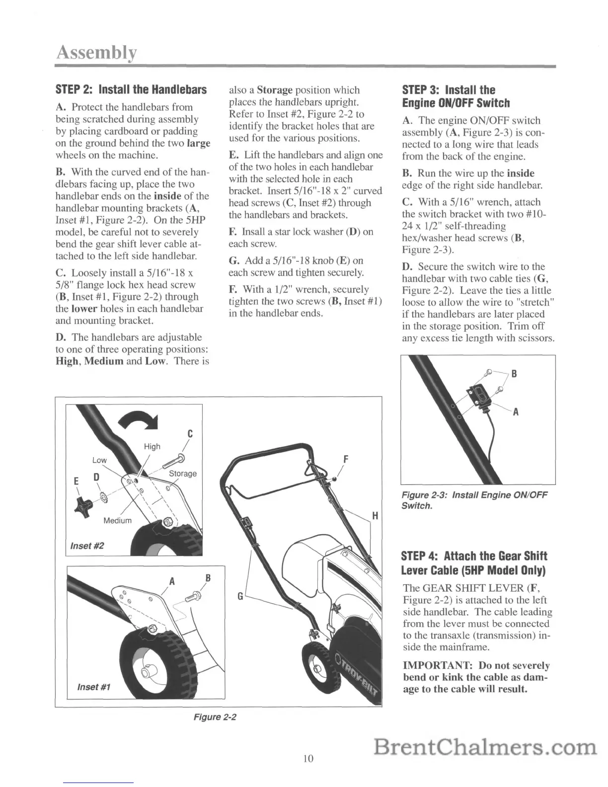
A. Protect the handlebars from
being scratched during assembly
by placing cardboard or padding
on the ground behind the two
large
wheels on the machine.
B. With the curved end
of
the han-
dlebars facing up, place the two
handlebar ends on the inside
of
the
handlebar mounting brackets (A,
Inset #1, Figure 2-2). On the 5HP
model, be careful not to severely
bend the gear shift lever cable at-
tached to the left side handlebar.
C. Loosely install a 5/16"-18 x
5/8" flange lock hex head screw
(B, Inset #1, Figure 2-2) through
the lower holes in each handlebar
and mounting bracket.
D. The handlebars are adjustable
to one
of
three operating positions:
High,
Medium
and Low. There is
E 0
\
~'
Medium
Inset
#2
also a
Storage
position which
places the handlebars upright.
Refer to Inset #2, Figure 2-2 to
identify the bracket holes that are
used for the various positions.
E. Lift the handlebars and align one
of
the two holes in each handlebar
with the selected hole
in each
bracket. Insert 5/16"-18 x
2"
curved
head screws (C, Inset #2) through
the handlebars and brackets.
F.
Insall a star lock washer (D) on
each screw.
G. Add a 5/16"-18 knob (E) on
each screw and tighten securely.
F.
With a 1/2" wrench, securely
tighten the two screws (B, Inset #1)
in the handlebar ends.
STEP
3:
Install
the
Engine
ON/OFF
Switch
A. The engine ON/OFF switch
assembly (A, Figure 2-3) is con-
nected to a long wire that leads
from the back
of
the engine.
B. Run the wire
up
the inside
edge
of
the right side handlebar.
C. With a 5/16" wrench, attach
the switch bracket with two #10-
24 x 1/2" self-threading
hex/washer head screws (B,
Figure 2-3).
D. Secure the switch wire to the
handlebar with two cable ties (G,
Figure 2-2). Leave the ties a little
loose to allow the wire to "stretch"
if the handlebars are later placed
in the storage position. Trim off
any excess tie length with scissors.
Figure 2-3: Install Engine ON/OFF
Switch.
STEP
4:
Attach
the
Gear
Shift
Lever
Cable
(5HP
Model
Only)
The GEAR
SHIFf
LEVER (F,
Figure 2-2) is attached to the left
side handlebar. The cable leading
from the lever must be connected
to the transaxle (transmission) in-
side the mainframe.
IMPORTANT:
Do
not
severely
bend
or
kink
the
cable
as
dam-
age to
the
cable will result.
Figure 2-2
10
 Loading...