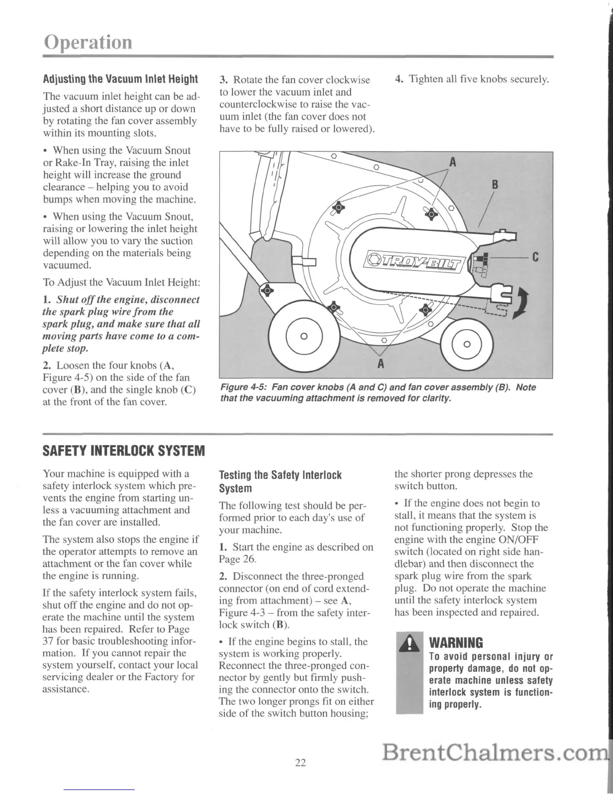
Figure 4-5: Fan
cover
knobs
(A
and
C)
and
fan
cover
assembly
(8).
Note
that
the vacuuming attachment
is
removed
for
clarity.
Operation
Adjusting
the
Vacuum
Inlet
Height
The vacuum inlet height can be ad-
justed a short distance
up
or down
by rotating the fan cover assembly
within its mounting slots.
• When using the Vacuum Snout
or Rake-In Tray, raising the inlet
height will increase the ground
clearance - helping you to avoid
bumps when moving the machine.
• When using the Vacuum Snout,
raising or lowering the inlet height
will allow you to vary the suction
depending on the materials being
vacuumed.
To
Adjust the Vacuum Inlet Height:
1.
Shut
off
the engine, disconnect
the spark plug wire from the
spark plug,
and
make sure that all
moving parts have come
to
a com-
plete stop.
2. Loosen the four knobs (A,
Figure 4-5) on the side
of
the fan
cover (B), and the single knob
(C)
at the front
of
the fan cover.
SAFETY
INTERLOCK
SYSTEM
Your machine is equipped with a
safety interlock system which pre-
vents the engine from starting un-
less a vacuuming attachment and
the fan cover are installed.
The system also stops the engine if
the operator attempts to remove an
attachment or the fan cover while
the engine
is
running.
If
the safety interlock system fails,
shut offthe engine and do not op-
erate the machine until the system
has been repaired. Refer to Page
37 for basic troubleshooting infor-
mation.
If
you cannot repair the
system yourself, contact your local
servicing dealer or the Factory for
assistance.
3. Rotate the fan cover clockwise
to lower the vacuum inlet and
counterclockwise to raise the vac-
uum inlet (the fan cover does not
have to be fully raised or lowered).
Testing
the
Safety
Interlock
System
The following test should be per-
formed prior to each day's use
of
your machine.
1. Start the engine as described on
Page 26.
2. Disconnect the three-pronged
connector (on end
of
cord extend-
ing from attachment) - see
A,
Figure 4-3 - from the safety inter-
lock switch (B).
•
If
the engine begins to stall, the
system
is
working properly.
Reconnect the three-pronged con-
nector by gently but firmly push-
ing the connector onto the switch.
The two longer prongs fit on either
side
of
the switch button housing;
22
4. Tighten all five knobs securely.
.t~r;;---C
the shorter prong depresses the
switch button.
•
If
the engine does not begin to
stall, it means that the system is
not functioning properly. Stop the
engine with the engine ON/OFF
switch (located on right side han-
dlebar) and then disconnect the
spark plug wire from the spark
plug. Do not operate the machine
until the safety interlock system
has been inspected and repaired.
WARNING
To
avoid personal injury
or
property
damage,
do
not
op-
erate
machine
unless
safety
interlock
system
is
function-
ing
properly.
 Loading...