Assembly
STEP
6:
Install
the
Chipper
Chute
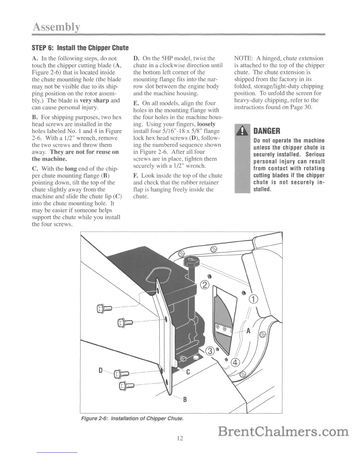
A.
In the following steps, do not
touch the chipper cutting blade (A,
Figure 2-6) that is located inside
the chute mounting hole (the blade
may not be visible due to its ship-
ping position on the rotor assem-
bly.) The blade
is
very
sharp
and
can cause personal injury.
B. For shipping purposes, two hex
head screws are installed in the
holes labeled
No.1
and 4 in Figure
2-6. With a 1/2" wrench, remove
the two screws and throw them
away. They
are
not for reuse
on
the
machine.
C. With the long end
of
the chip-
per chute mounting flange (B)
pointing down, tilt the top of the
chute slightly away from the
machine and slide the chute lip
(C)
into the chute mounting hole. It
may
be
easier
if
someone helps
support the chute while you install
the four screws.
D.
On the 5HP model, twist the
chute
in
a clockwise direction until
the bottom left corner
of
the
mounting flange fits into the nar-
row slot between the engine body
and the machine housing.
E. On all models, align the four
holes
in
the mounting flange with
the four holes
in
the machine hous-
ing. Using your fingers, loosely
install four 5/16"-18 x 5/8" flange
lock hex head screws (D), follow-
ing the numbered sequence shown
in
Figure 2-6. After all four
screws are in place, tighten them
securely with a 1/2" wrench.
F.
Look inside the top
of
the chute
and check that the rubber retainer
flap
is
hanging freely inside the
chute.
NOTE: A hinged, chute extension
is attached to the top
of
the chipper
chute. The chute extension
is
shipped from the factory in its
folded, storage/light-duty chipping
position.
To
unfold the screen for
heavy-duty chipping, refer to the
instructions found on Page 30.
DANGER
Do
not
operate
the
machine
unless
the
chipper
chute
is
securely
installed.
Serious
personal injury
can
result
from contact with rotating
cutting
blades
if
the
chipper
chute is not securely in-
stalled.
(f)p--
(f)p--
D
(f)p--
(f)p--
Figure 2-6: Installation
of
Chipper Chute.
12
 Loading...