Route
Gear
Shift
lever
Cable
BELOW
Handlebar.
A.
With a 3/8" wrench, remove the
three self-threading screws from
the transaxle access cover
(A,
Figure 2-4) located on the rear
of
the mainframe. Remove the cover.
B. Move the GEAR SHIFT
LEVER (F, Figure 2-2) to the No.
4 setting as indicated on the decal
(push lever all the way forward
until it stops moving).
C. With a 3/8" wrench, loosen the
cable clamp screw (B, Figure 2-4)
and swing the cable clamp
(C)
to
one side.
IMPORTANT:
The
transaxle
shifting
arm
(D,
Figure
2·4) is
preset
in
4th
gear. Do
not
move
the
shifting
arm
before installing
the
cable.
D. Gently route the cable (E,
Figure 2-4) below the handlebar
and insert the "Z" hook end
of
the
cable wire into the top
of
the
transaxle shifting arm (D).
E. Place the cable sheath
in
the
groove on the top
of
the transaxle
and swing the clamp over the
cable. Check that the GEAR
SHIFT LEVER (on handlebar) is
still in the
No.4
setting. Then,
tighten the clamp screw securely.
F.
Check the function
of
the cable
by
moving the GEAR SHIFT
LEVER all the way back to P
(Park) and then all the way forward
to
No.4.
You
should feel the lever
engage seven distinct positions
(with six "clicks" in between).
If
not, repeat Steps B through
F.
NOTE: Be sure that the cable
sheath does not move within the
clamp while performing this test.
I---:.W'--------lo
E
Assembly
G. Reinstall the transaxle access
cover with the three cover mount-
ing screws removed previously.
NOTE: Put the GEAR SHIFT
LEVER
in
N (Neutral) to move the
machine without the engine run-
ning. (A certain amount
of
stiff-
ness or drag
is
normal when the
machine
is
moved
in
Neutral.)
o
t
A
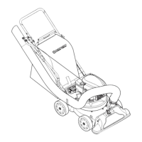
Figure 2-4:
Install
Gear
Shift
Lever
Cable.
STEP
5:
Attach
the
Wheel
Drive
Bail
Cable
(5HP
Model
Only)
A.
The wheel drive bail cable (A,
Figure 2-5)
is
connected to the
bracket on the rear, left side of the
mainframe. Run the cable
up
the
inside edge of the left side handle-
bar and align the hole
in
the cable
clamp (B) with the
upper
of
the
two holes that are located a few
inches below the GEAR SHIFT
LEVER.
B. Insert a 1/4"-20 x 1-5/8" curved
head screw (C, Figure 2-5)
through the handlebar and into the
clamp. Add a 1/4"-20 flanged
locknut (D) and tighten securely
using a 7/16" wrench.
C. Slip the cable eyelet (E, Figure
2-5) over the stud (F) on the wheel
drive bail. Place a wood block be-
hind the stud and use a hammer
to
tap the cap push nut (G) onto the
stud (the push nut can also be
pressed on with a pair
of
large-
sized pump or parallel jaw pliers).
D. Secure the gear shift lever
cable and the wheel drive bail
cable to the handlebar with two
cable ties (H, Figure 2-2). Leave
the ties a little loose to allow the
cables to "stretch" if the handle-
bars are later placed in the storage
position. Trim off any excess tie
length with scissors.
11
C
~
--
Figure 2-5:
Install
Wheel
Drive
Bail
Cable.
 Loading...