Operation
REMOVING
OR
CHANGING
A
SHREDDER
SCREEN
The standard, 1-1/8" slotted shred-
der
screen (A, Figure 4-6) is fac-
tory-installed inside the processing
chamber. A 3/4" slotted screen is
an option. The size
of
the slots
help determine how finely the ma-
terial
is
shredded (see "Shredder
Screens," Page 16).
When
necessary, the screen is eas-
ily removed without tools.
The use
of
the screen will vary ac-
cording to the materials being pro-
cessed, as explained
in
the vacu-
uming and chipping operating in-
structions
in
this Section.
SPECIAL
OPERATING
TIPS:
•
If
vacuuming hard materials
such as bark nuggets, hickory nuts,
sweet gum tree balls, etc., first re-
move the screen to prevent possi-
ble damage to the screen.
•
If
vacuuming wet
or
heavy mate-
rials (damp leaves, matted debris,
etc.)
or
difficult materials (acorns,
pine needles, etc.), first remove the
screen to improve air flow and to
avoid clogging.
Removing
a
Shredder
Screen
1.
Shut
off
the engine, disconnect
the spark plug wire from the
spark plug, and make sure that all
moving parts have come
to
a com-
plete stop.
2. Disconnect the safety interlock
cord and remove the vacuuming
attachment (see "Removing An
Attachment," Page
21).
3. Remove the fan cover (B, Figure
4-6) by loosening the single knob
(C) at the front
of
the cover and
then removing the four knobs (D)
on the side
of
the cover.
4. Remove the screen, being care-
ful to avoid any sharp edges on the
fan blades
or
the screen.
5. To operate the machine without
a screen installed, replace the fan
cover assembly as described in
Steps 3 through 5
of
the following
installation procedure.
Installing
a
Shredder
Screen
1. Follow the instructions outlined
in Steps
1,
2 and 3
of
"Removing a
Shredder Screen."
2. Align the four holes in the
screen mounting flange with the
four studs on the machine, and
slide the screen into the chamber.
3. Insert the fan cover behind the
fan cover retaining bracket (E,
Figure 4-6) and install the fan
cover on the four studs. Rotate the
fan cover clockwise, making sure
the mounting bracket at the front is
aligned with the front knob (C,
Figure 4-6).
4. Loosely reinstall the four knobs
(D). The
€Over
can be adjusted a
short distance up
or
down (see
"Adjusting the Vacuum Inlet
Height" on Page 22). After mak-
ing any adjustments, securely
tighten the four knobs, followed by
the single knob
(C).
5. Reinstall a vacuuming attach-
ment and reconnect the safety in-
terlock cord before resuming
operation.
DANGER
Rotating
cutting
blades
will
cause
serious
injury.
• Before removing
or
in-
stalling a
shredder
screen,
stop engine, disconnect
spark
plug
wire
from
spark
plug,
and
make
sure
that
all
moving
parts
have
come
to
a
complete
stop.
•
Do
not
operate
machine
unless
fan
cover
is
securely
installed.
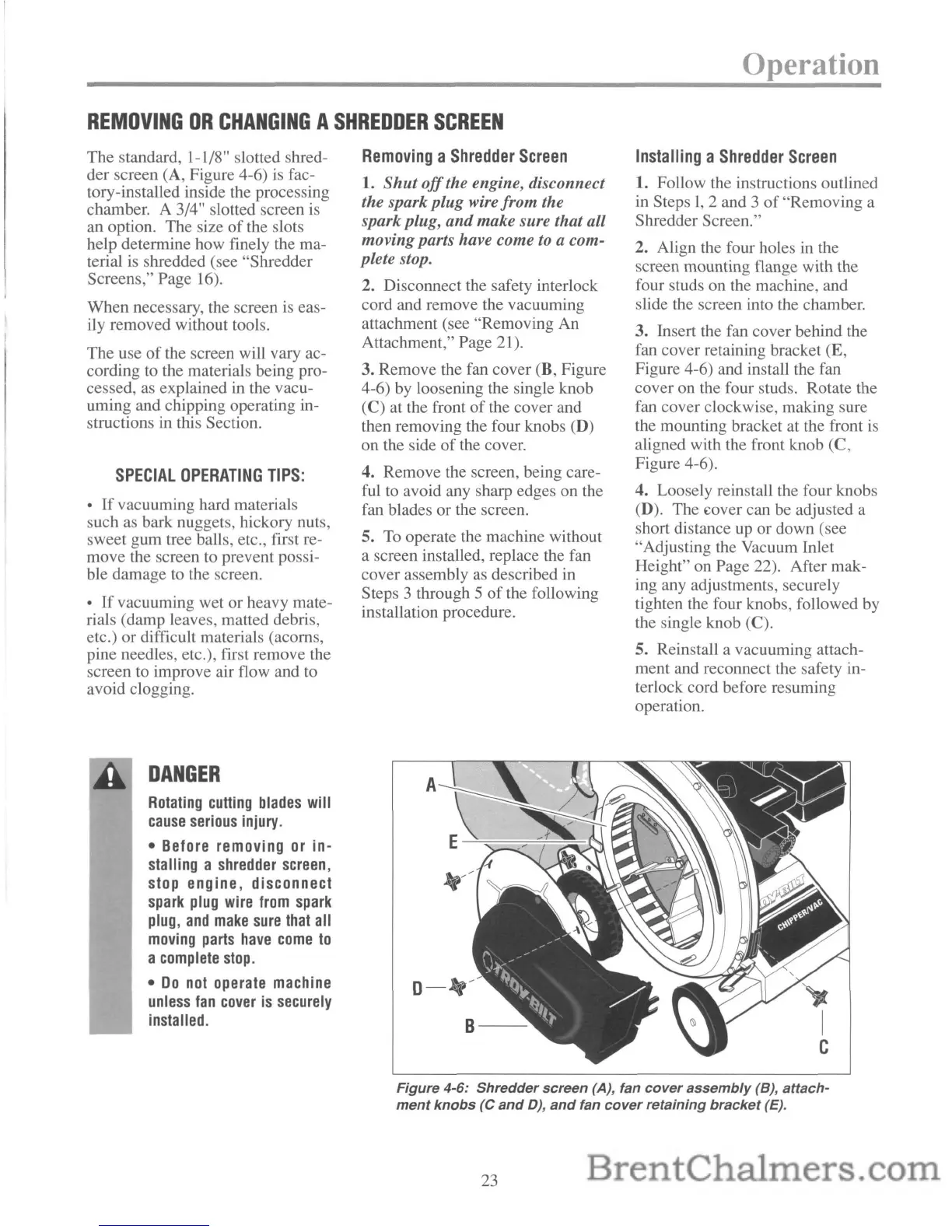
Figure 4-6: Shredder screen (A), fan
cover
assembly
(B), attach-
ment
knobs
(C
and
D),
and
fan
cover
retaining
bracket
(E).
23
 Loading...