Maintenance/Repairs
REPLACING
THE
WHEEL
DRIVE
BAIL
CABLE
(5HP
MODEL
ONLY)
The following instructions de-
scribe how to install a new wheel
drive bail cable.
1.
Shut
off
the engine, disconnect
the spark plug wire from the
spark plug, and make sure that all
moving parts have come to a com-
plete stop.
2. With a 3/8" wrench, remove the
three self-threading screws from
the transaxle access cover that is
located on the rear, left side
of
the
frame. Place the screws and cover
aside.
3. Cut and remove the cable tie on
the left side handlebar.
4. With a 1/2" wrench, unthread
the lower
jam
nut (A, Figure 5-13)
from the old cable adjuster (B).
5. Remove the cap push nut that
secures the eyelet at the upper end
of
the cable wire to the stud on the
wheel drive bail. See Inset #5,
Figure 2-2, on Page
11.
6. With a 7/16" wrench, remove
the upper cable clamp on the inside
edge
of
the handlebar by removing
the curved head screw and locknut.
7. Unhook the cable tension
spring (C) from the idler arm (D).
8. Pull the cable up through the
hole in the frame and slide the
cable wire out through the slot in
the cable bracket (E).
9. The new cable
is
shipped with
the lower
jam
nut (A) loose. Hold
onto the lower
jam
nut and insert
the cable tension spring (C) into
the hole in the frame.
10. Hold the lower
jam
nut (A)
below the cable bracket (E) and in-
sert the cable wire at the bottom
of
the adjuster (B) into the slot in the
cable bracket. Insert the adjuster
halfway through the hole in the
bracket and then thread the lower
jam
nut onto the cable adjuster.
11. Attach the cable tension spring
(C)
to the idler arm (D).
The
open
side
of
the spring hook must be fac-
ing the inside
of
the frame (toward
the transaxle).
12. Run the cable sheath up the in-
side edge
of
the handlebar and se-
cure the upper cable clamp to the
upper
of
the two holes in the
handlebar.
13. Slip the eyelet at the end
of
the
cable wire onto the stud on the
wheel drive bail and secure it with
a new cap push nut.
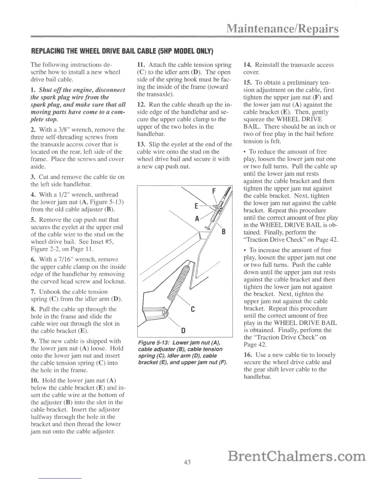
Figure 5-13:
Lower
jam
nut
(A),
cable
adjuster
(B), cable tension
spring
(e),
idler
arm
(D), cable
bracket
(E),
and
upper
jam
nut
(F).
43
14. Reinstall the transaxle access
cover.
15. To obtain a preliminary ten-
sion adjustment on the cable, first
tighten the upper
jam
nut (F) and
the lower
jam
nut (A) against the
cable bracket (E). Then, gently
squeeze the
WHEEL
DRIVE
BAlL. There should
be
an inch
or
two
of
free play in the bail before
tension is felt.
• To reduce the amount
of
free
play, loosen the lower
jam
nut one
or
two full turns. Pull the cable up
until the lower
jam
nut rests
against the cable bracket and then
tighten the upper
jam
nut against
the cable bracket. Next, tighten
the lower
jam
nut against the cable
bracket. Repeat this procedure
until the correct amount
of
free play
in the
WHEEL
DRIVE
BAlL
is
ob-
tained. Finally, perform the
"Traction Drive Check"
on
Page 42.
• To increase the amount
of
free
play, loosen the upper
jam
nut one
or two full turns. Push the cable
down until the upper
jam
nut rests
against the cable bracket and then
tighten the lower
jam
nut against
the bracket. Next, tighten the
upper
jam
nut against the cable
bracket. Repeat this procedure
until the correct amount
of
free
play in the
WHEEL
DRIVE
BAlL
is obtained. Finally, perform the
the "Traction Drive Check" on
Page 42.
16. Use
anew
cable tie to loosely
secure the wheel drive cable and
the gear shift lever cable to the
handlebar.
 Loading...