Features and Controls
I
Wire
Hoop
Debris
Guard
/
---0
---
Recoil
Starter
5HP
MODEL
Spark
Plug
/
Oil
Fill/Dipstick
\-r
Oil
Drain
?
Choke
/'
Air
Cleaner
Debris
Guard
/
----0
---
I
Wire
Hoop
4HP
MODEL
Recoil
Starter
\
Oil
Drain
Spark
Plug
\
Muffler
Chok'\
\
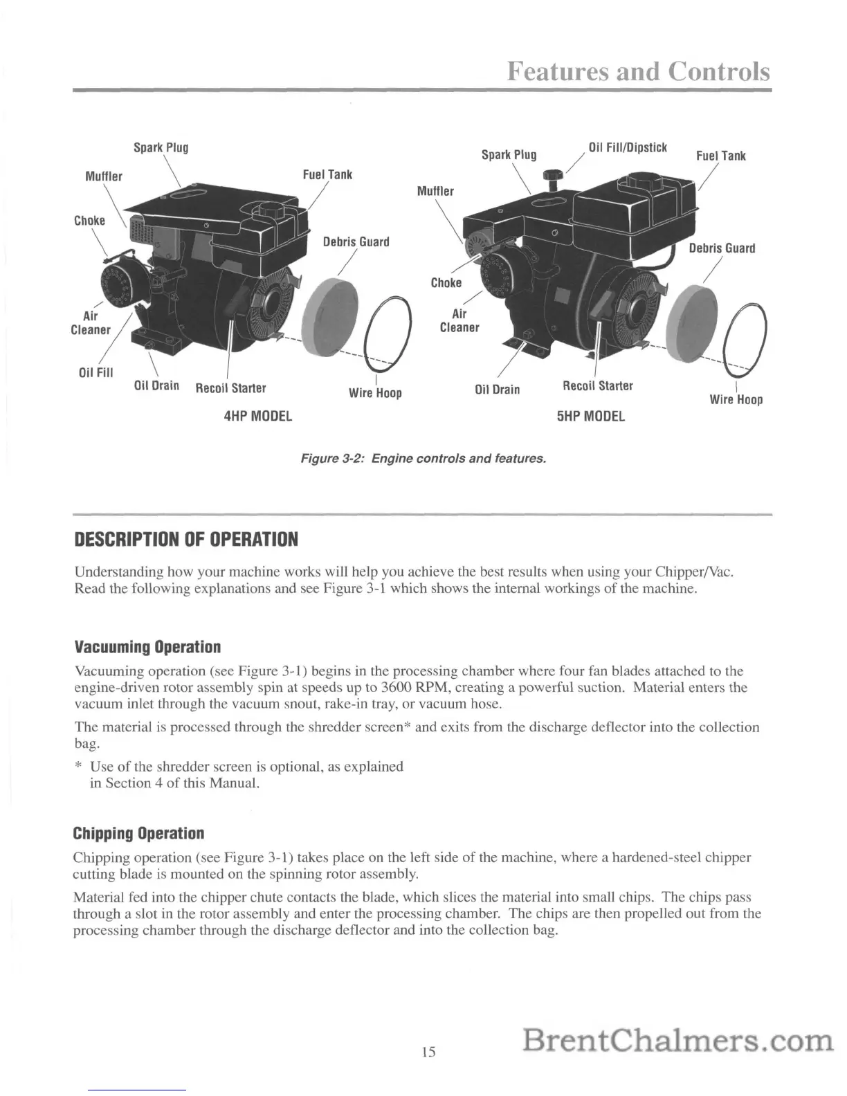
Figure 3-2: Engine
controls
and
features.
DESCRIPTION
OF
OPERATION
Understanding how your machine works will help you achieve the best results when using your ChipperNac.
Read the following explanations and see Figure 3-1 which shows the internal workings
of
the machine.
Vacuuming
Operation
Vacuuming operation (see Figure 3-1) begins in the processing chamber where four fan blades attached to the
engine-driven rotor assembly spin at speeds up to 3600 RPM, creating a powerful suction. Material enters the
vacuum inlet through the vacuum snout, rake-in tray, or vacuum hose.
The material is processed through the shredder screen* and exits from the discharge deflector into the collection
bag.
* Use
of
the shredder screen is optional, as explained
in Section 4
of
this Manual.
Chipping
Operation
Chipping operation (see Figure 3-1) takes place on the left side
of
the machine, where a hardened-steel chipper
cutting blade is mounted on the spinning rotor assembly.
Material fed into the chipper chute contacts the blade, which slices the material into small chips. The
chips pass
through a slot in the rotor assembly and enter the processing chamber. The chips are then propelled out from the
processing chamber through the discharge deflector and into the collection bag.
15
 Loading...