UTD1000L User Manual
7
or the local office of UNI-T.
If any damage of accessory surface, or failure to
work or to pass the function test were found, please
contact with the UNI-T distributor or the local
representative office of UNI-T.
If any damage were found, please keep the
package and contact with the transportation
department and the uni-t distributor that sells the
product, UNI-T shall arrange for the maintenance or
replacement.
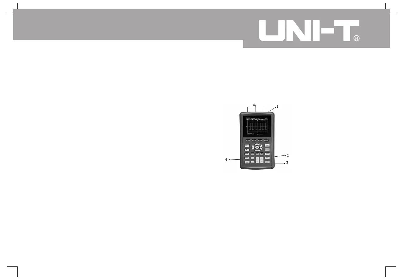
The oscilloscope connection is referred to the
picture 3-1
1. Oscilloscope channel input port
2. USB connection port.
3. Adapter interface used for AC power supply and
battery charging.
4. Probe compensation signal output port
5. Multimeter input socket 3 circular banana
sockets are input ports for voltabe resistance
current and COM port
Check the Complete Apparatus
Oscilloscope Connection
Instructions
Oscilloscope Connection
:
,
/,
.
Picture 3-1 Oscilloscope Interface
 Loading...