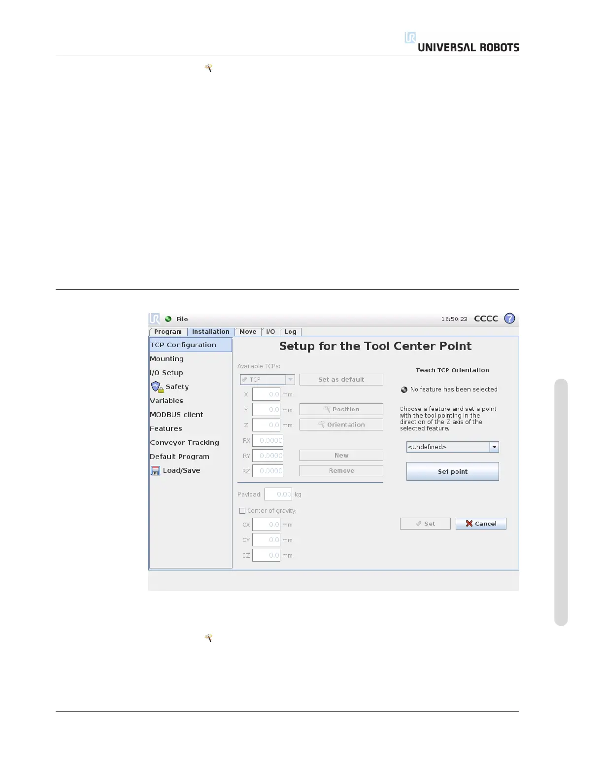
12.6 Installation → TCP Configuration
1. Tap the Position button.
2. Choose a fixed point in the workspace of the robot.
3. Use the buttons on the right side of the screen to move the TCP to the chosen
point from at least three different angles and to save the corresponding positions
of the tool output flange.
4. Verify the calculated TCP coordinates and set them onto the selected TCP using
the Set button.
Note that the positions must be sufficiently diverse for the calculation to work cor-
rectly. If they are not, the status LED above the buttons turns red.
Furthermore, even though three positions are usually sufficient to determine the cor-
rect TCP, the fourth position can be used to further verify that the calculation is correct.
The quality of each saved point with respect to the calculated TCP is indicated using
a green, yellow or red LED on the respective button.
12.6.4 Teaching TCP orientation
TCP orientation can be calculated automatically as follows:
1. Tap the Orientation button.
2. Select a feature from the drop-down list. For additional information about how
new features can be defined, see 12.12.
Version 3.1 (rev. 17782)
Copyright © 2009-2015 by Universal Robots A/S. All rights reserved.
II-25 CB3

 Loading...


