3 Mechanical Interface
The robot consists essentially of six robot joints and two aluminum tubes, connecting
the base with the tool of the robot. The robot permits the tool to be translated and
rotated within the workspace. The next section describes the basics of mounting the
various parts of the robot system.
Electrical installation instructions in chapter 4 must be observed.
3.1 Workspace of the Robot
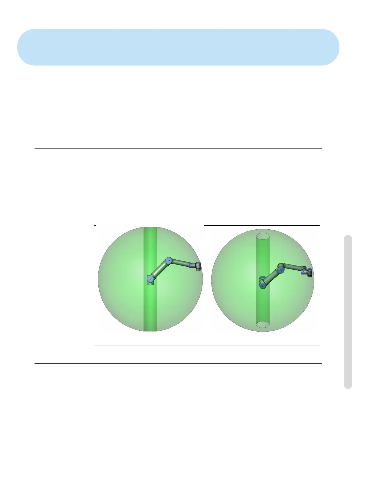
The workspace of the UR5 robot extends 850 mm from the base joint. It is important
to consider the cylindrical volume directly above and directly below the robot base
when a mounting place for the robot is chosen. Moving the tool close to the cylin-
drical volume should be avoided if possible, because it causes the joints to move fast
even though the tool is moving slowly, causing the robot to work inefficiently and the
conduction of the risk assessment to be difficult.
Front Tilted
3.2 Mounting
Robot Arm The robot arm is mounted using four M8 bolts, using the four 8.5 mm
holes on the base. It is recommended to tighten these bolts with 20 N m torque. If
very accurate repositioning of the robot arm is desired, two Ø8 holes are provided for
use with a pin. Also, an accurate base counterpart can be purchased as an accessory.
Figure 3.1 shows where to drill holes and mount the screws.
Version 3.1 (rev. 17782)
Copyright © 2009-2015 by Universal Robots A/S. All rights reserved.
I-13 UR5/CB3

 Loading...


