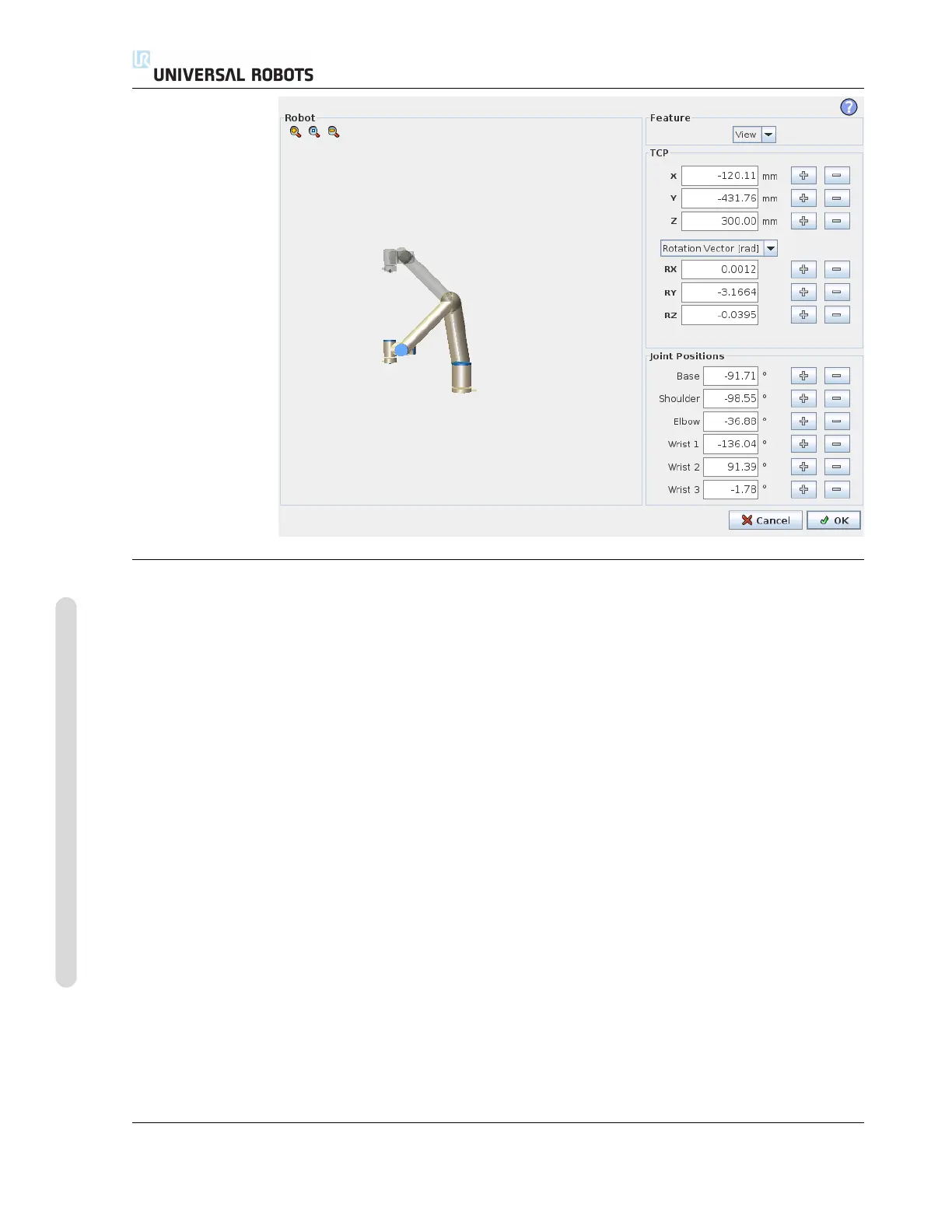
11.4 Pose Editor Screen
Robot
The current position of the robot arm and the specified new target position are shown
in 3D graphics. The 3D drawing of the robot arm shows the current position of the
robot arm, and the “shadow” of the robot arm shows the target position of the robot
arm controlled by the specified values on the right hand side of the screen. Push the
magnifying glass icons to zoom in/out or drag a finger across to change the view.
If the specified target position of the robot TCP is close to a safety or trigger plane, or
the orientation of robot tool is near the tool orientation boundary limit (see 15.11), a
3D representation of the proximate boundary limit is shown.
Safety planes are visualized in yellow and black with a small arrow representing the
plane normal, which indicates the side of the plane on which the robot TCP is allowed
to be positioned. Trigger planes are displayed in blue and green and a small arrow
pointing to the side of the plane, where the Normal mode limits (see 15.5) are active.
The tool orientation boundary limit is visualized with a spherical cone together with
a vector indicating the current orientation of the robot tool. The inside of the cone
represents the allowed area for the tool orientation (vector).
When the target robot TCP no longer is in the proximity of the limit, the 3D represen-
tation disappears. If the target TCP is in violation or very close to violating a boundary
limit, the visualization of the limit turns red.
CB3 II-14 Version 3.1 (rev. 17782)
Copyright © 2009-2015 by Universal Robots A/S. All rights reserved.

 Loading...


