110
Cooling system
6
Check the components for signs of damage and re-
place if necessary.
7
Slide the sleeve (A1) on the end of the insert until
the insert is in contact with the reduced diameter of
the sleeve.
8
Press a rubber end (A2) over the other end of the
insert until the protrusion inside the rubber end
touches the end of the sleeve.
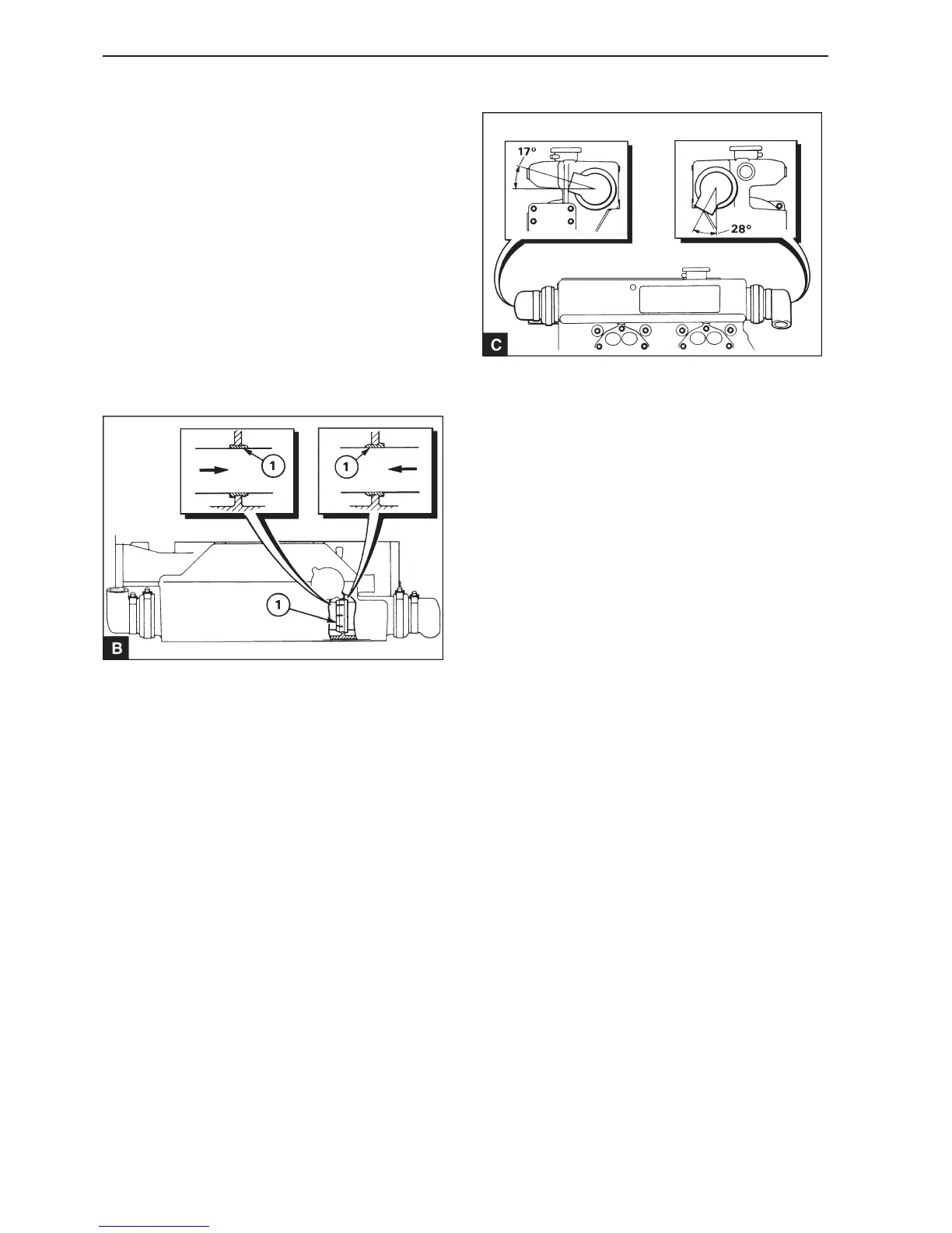
9
Install the second rubber end. Check that the pipe
connectors of the rubber ends are in the correct po-
sition and tighten the clamps. Place the rubber ends
in the positions shown in C if the assembly has be
removed from the engine.
11
Connect the sea water intake and outlet pipes to the
heat exchanger. The output pipe must be pushed in
so that the end of the pipe is in the center of rubber
end of the heat exchanger. Tighten the clamp to the
outlet pipe.
12
Fill the coolant circuit, operation 20A-02 and open
the seacock.
13
Run the engine and check for leakage.
If a rubber sleeve is used, lubricate it with a little
soap solution. Place the sleeve end of the assembly
in the housing and carefully insert the sleeve in the
hole in the baffle plate Carefully press the pipe ends
of the housing until the journal in the housing is cor-
rectly positioned inside the end cover. Do not pull
the pipe cluster backwards during installation, as
this pulls the sleeve out of the baffle plate. Check
through the filler opening that the sleeve is posi-
tioned correctly in the baffle plate (B).
10
 Loading...