30
Cylinder head
Valve guides, inspection
(12A-10)
Special tools: 885021, 885022
Check the valve guides for wear. The maximum
play between the valve stem and the hole in the
guide is 0.13 mm. If the clearance is greater when a
new valve is installed, a new valve guide must be
installed.
6
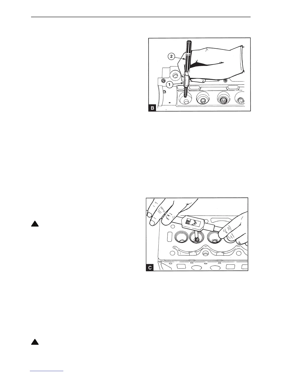
Install the guide B1 on the thin end of the tool
885021 (B2) with the bevel turned to the thin end of
the tool (B). Insert the bevelled end of the guide into
position in the cylinder head and press in the guide
until the tool end comes into contact with the flat
plate. Check that the guide protrudes 10 mm above
the mating surface for the valve spring.
7
Allow the cylinder head to cool.
8
Ream the hole for the new guide using reamer
885022 (C).
Valve guides, replacement
(12A-11)
1
Ensure that the surface of the cylinder head and the
storage surface in a suitable press are clean.
2
Heat the whole cylinder head slowly and evenly to
approximately 100°C and lay the head with the sur-
face downwards. Ensure that the surface is not
damaged during handling.
WARNING! Use suitable gloves as protection
against the hot metal.
3
Install the thin end of tool 885021 in the guide and
press it out. Repeat the procedure if several guides
need to be replaced.
4
Clean the valve guide position and ensure that it is
not damaged.
5
Heat the whole cylinder head slowly and evenly to
approximately 100°C. Lay the head in the press with
the surface downward with a flat surface located un-
der the valve opening. Ensure that the head surface
is not damaged during handling.
WARNING! Use suitable gloves as protection
against the hot metal.
 Loading...