18
Check that the groove in the camshaft cover and
the mating surfaces on the cylinder head and cover
are clean. Apply a 2mm bead of silicon in the outer
groove of the cover, but leave the inner groove
empty as illustrated in illustration (C). Install the
cover directly after the sealant has been applied. In-
stall the mounting screws with the longer screws in
each end of the cover. Tighten the screws in stages
in order to hold the cover parallel to the cylinder
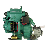
head when it is tightened. Finally tighten the screws
to 22 Nm in the order displayed in the illustration
(D).
9
Install and tighten the screw securing the seawater
pump drive housing to the camshaft cover. If the in-
stallation bracket for the seawater pump has been
removed, align the bracket before tightening it see
operation 20A-08.
10
Install and tighten the screws securing the timing
cover to the camshaft cover. Install the cover to
the timing cover if required.
11
Ensure that the adjustment hole in the front of the
camshaft front bearing journal corresponds with the
hole in the camshaft cover. Install the fuel supply
pump, operation 19A-03. Install the screw in the ad-
justing hole in the camshaft cover. Install the engine
lifting brackets.
Valve clearance, check
(12A-02)
Special tools: 885025, 885024
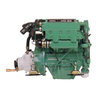
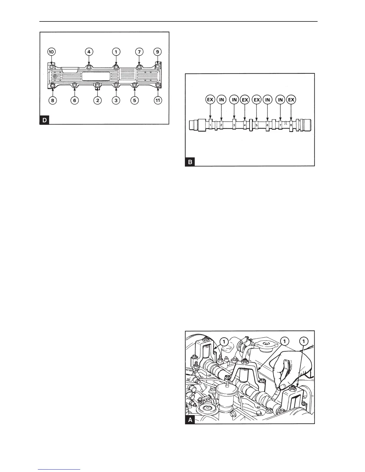
The valve clearance is measured between the cam-
shaft and the upper side of the valve lifter (A). With
a cold engine the correct valve clearance 0.25-0.35
mm for the inlet valves and 0.35 –0.45 mm for the
exhaust valves. See B for the position for the inlet
and exhaust cams.
Cam no.1 is at the camshaft pulley end.
1
Disconnect the battery.
2
Remove the camshaft cover, operations 12A-01.
Dismantle the seawater pump, operation 20A-06
and install the camshaft lock 885025 before the
cover is removed.
3
Cylinder head
 Loading...