114
Flywheel, flywheel cover
Flywheel cover, replacement
(21A-3)
Special tools: 885030
1
Remove the drive components from the rear end of
the engine.
2
Remove the starter motor, operation 22B-01. En-
gines with reverse gear: Remove the adapter hous-
ing for the reverse gear.
3
Remove the flywheel, operation 21A-01.
4
Remove the mounting screws for the flywheel cov-
er. Use a hammer with a soft face to detach the fly-
wheel cover from the guide pins.
5
Check that rear surface of the cylinder block and
the surfaces of the flywheel cover are clean and un-
damaged.
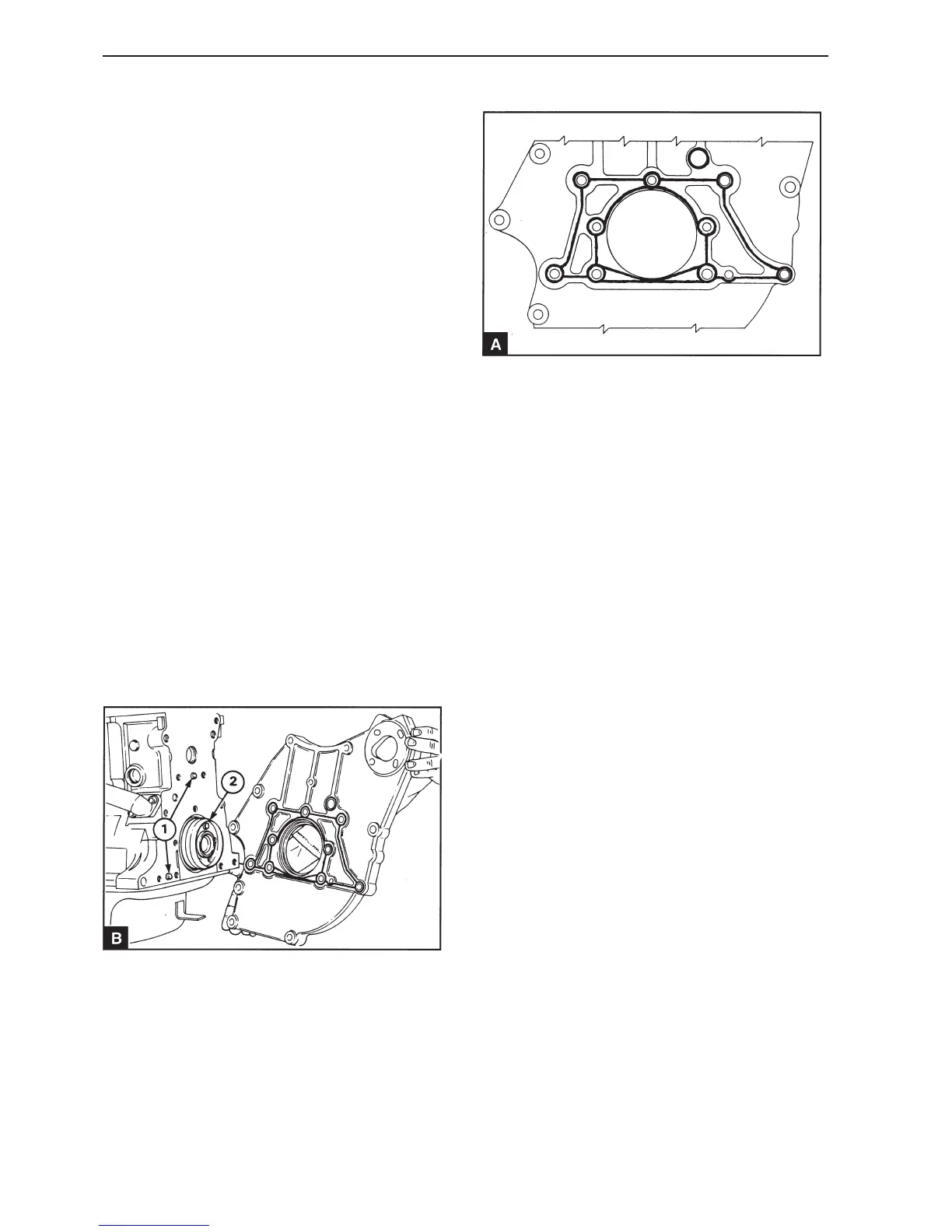
6
Check that the guide pins (B1) are correctly in-
stalled. Check that the outer diameter of the crank-
shaft flange is clean. Install the protective sleeve
for the stuffing box (B2) in position on the crank-
shaft flange. Lightly lubricate the outer diameter of
the crankshaft flange and the protective sleeve with
fresh engine oil.
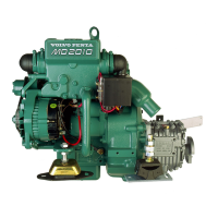
7
Apply a continuous 1.5 mm line of sealant on the
front surface of the cover, as shown in illustration
A. This operation is not necessary if a separate
housing is installed for the stuffing box.
8
Install the cover on the guide pins and tighten the
mounting screws.
Only reverse gear and S-drive
9
Check the concentricity of the cover using a dial in-
dicator. The maximum permissible total reading on
the indicator dial is 0.15 mm. If adjustment is nec-
essary, this must be carried out on the cover and
then the concentricity must be checked again.
10
Tighten the mounting screws evenly in stages with
the appropriate torque, as stated in section 11B,
and in the order shown in illustration 21A.05/A.
11
Check the axial run-out of the rear section of the
cover. The maximum permissible total reading on
the indicator dial is 0.15 mm. Any adjustments must
be carried out on the cover, not the cylinder block.
 Loading...