32
Cylinder head
Valve seat, grinding (12A-13)
1
If the valve guide is worn it should be replaced, op-
eration 12A-11.
2
Install the locating pin in the valve guide and tighten
it.
3
14
Valve seats with more serious damage can be cor-
rected using a milling tool, operation 12A-13 or a
new valve seats can be installed, operation 12A-14.
15
Install the valve springs and valves, operation 12A-
08.
16
Install the camshaft cover, operation 12A-01 and
the camshaft. Install the valve lifters and shims in
their correct positions. Install the camshaft in posi-
tion and check the valve clearance, operation 12A-
02 and adjust as necessary, operation 12A-03.
17
Install the seawater pump, operation 20A-06.
18
Install the thermostat housing.
19
Install the cylinder head assembly, operation 12A-
07.
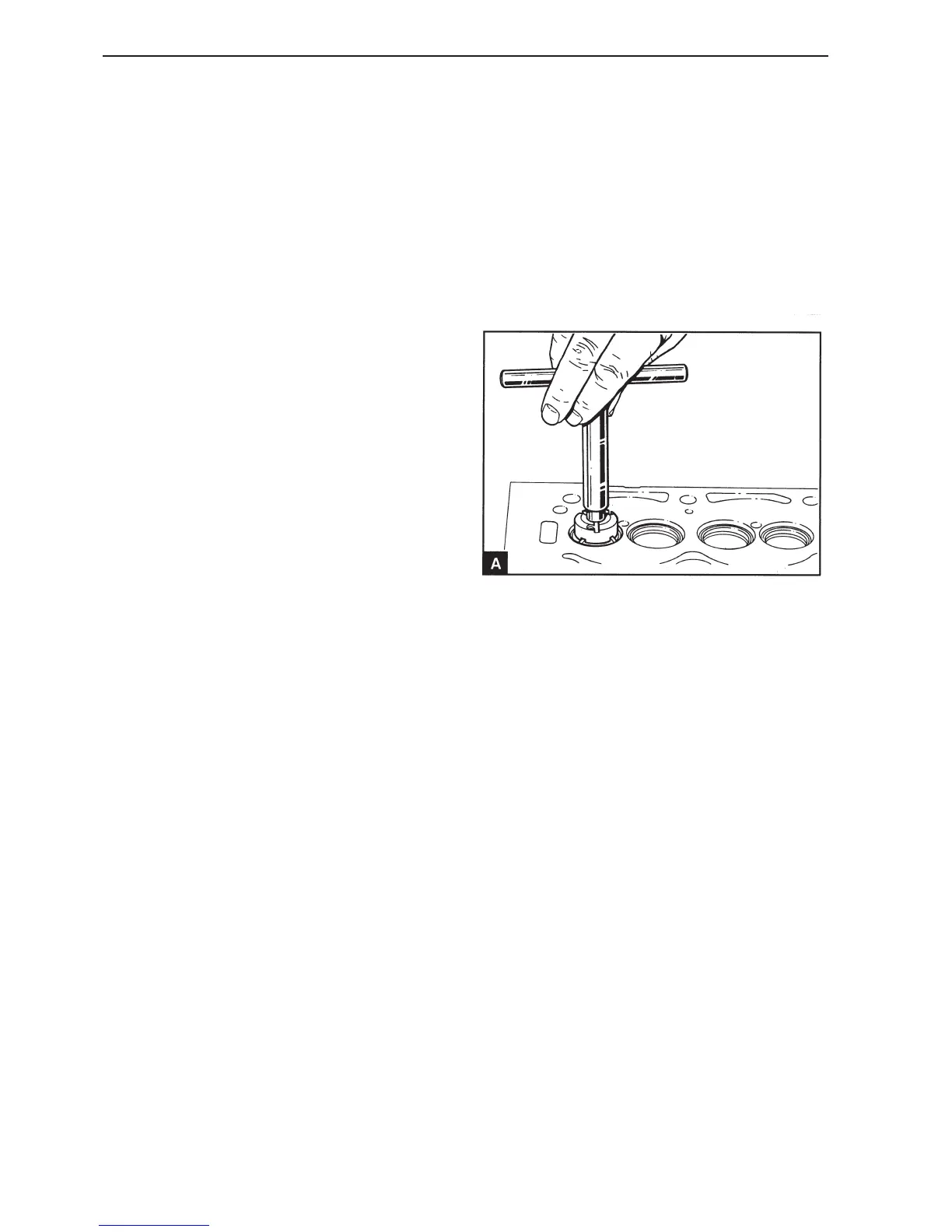
Install the mill on the locating pin with 46° side
against the valve seat and install the handle (A). Do
not let the mill head fall down towards the seat, this
can damage the blade.
4
Turn the mill carefully clockwise. Only remove as
much material as is necessary to achieve a seal.
Keep the sealing area as thin as possible.
5
Remove the mill and the locating pin when a satis-
factory sealing area has been achieved. Remove all
the work remnants from the area around the valve
seat and valve opening.
6
Install the valve and lightly lap the valve and seat.
7
Check that valve depth lies within the permitted pa-
rameters, see Workshop Manual “Technical Data”.
If a valve seat has become too damaged or worn it
must be replaced, operation 12A-14.
 Loading...