6-4 BA 1404 en – Edition 2.7 * * 1404b610.fm
Technical data
6.7 Electrical system
Fuses on control lever base on the left
Main fuse and relays in the engine compartment
Electrical system
Dynamo (optional alternator up to serial no.
WNCE0901CPAL00410)
12 V 20 A
Alternator (standard from WNCE0901CPAL00411) 12 V 40 A
Starter 12 V 1.1 kW (1.5 hp)
Battery (up to serial no. AF05342) 12 V 45 oh
Battery (from serial no. AF05343) 12 V 44 Ah
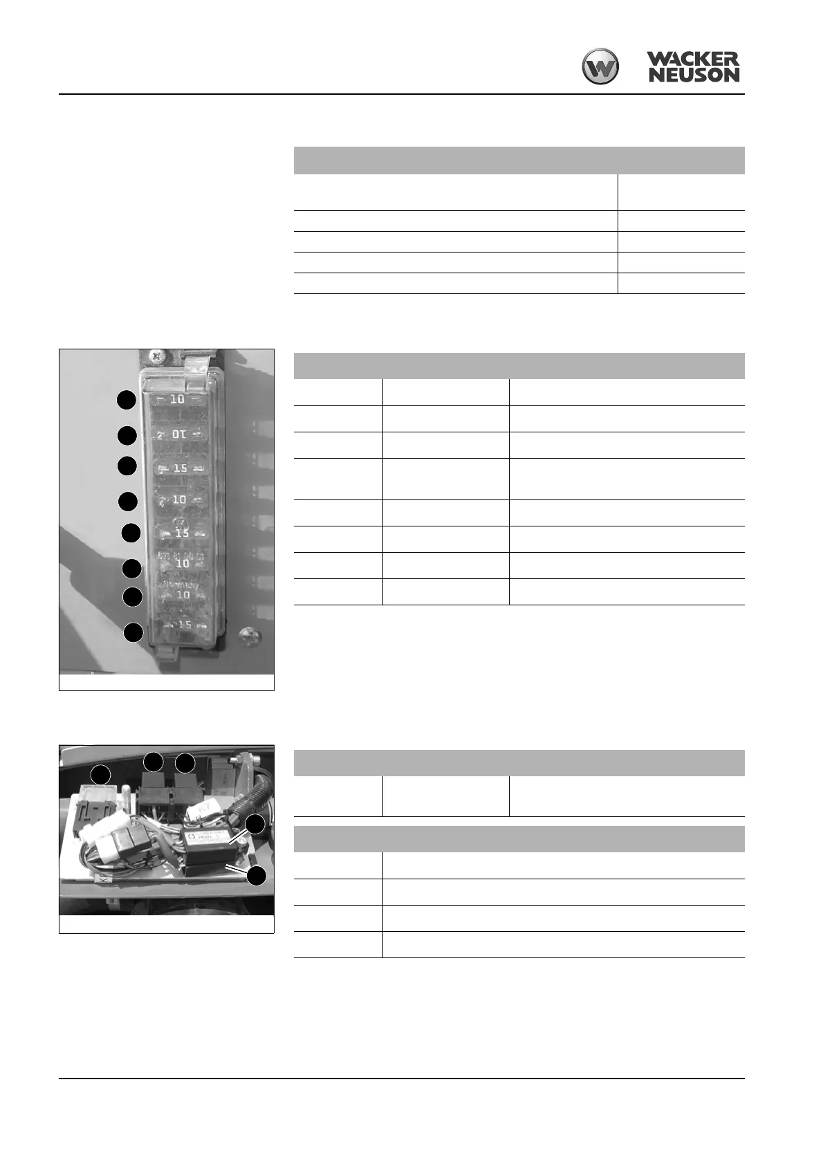
Abb. 216: Fuses
F2
F3
F4
F5
F6
F7
F8
F9
Fuse no. Rated current (A) Protected circuit
F2 10 A Fuse: relay, indicator, cutoff solenoid
F3 10 A Boom working light fuse
F4 15 A Cabin working light fuse
F5 10 A
Safety valves, horn, driving signal (option),
speed level 2
F6 15 A Heating fuse
F7 10 A Wiper and interior light fuse
F8 10 A Rotating beacon, radio and drive interlock fuse
F9 15 A Socket and 12 V power outlet fuse
Abb. 217: Relays
K8
K7
K9
F1
K6
Fuse no. Rated current (A) Protected circuit
F1 40 A
Main fuse; air-pressure sensor/output adap-
tation (Yanmar 3TNV80F-SSNS2)
Relay no. Protected circuit
K 6 Preheating time lag relay
K7 Start switching relay
K8 Time lag relay 1s cut-off solenoid
K9 Cut-off solenoid switching relay
 Loading...