VC707 Evaluation Board www.xilinx.com 109
UG885 (v1.4) May 12, 2014
Appendix D
Board Setup
Installing VC707 Board in a PC Chassis
Installation of the VC707 board inside a computer chassis is required when developing or
testing PCI Express functionality.
When the VC707 board is used inside a computer chassis (that is, plugged in to the PCIe®
slot), power is provided from the ATX power supply 4-pin peripheral connector through
the ATX adapter cable shown in Figure D-1 to J18 on the VC707 board. The Xilinx part
number for this cable is 2600304.
To install the VC707 board in a PC chassis:
1. On the VC707 board, remove all six rubber feet and standoffs. The standoffs and feet
are affixed to the board by screws on the top side of the board. Remove all six screws.
2. Power down the host computer and remove the power cord from the PC.
3. Open the PC chassis following the instructions provided with the PC.
4. Select a vacant PCIe expansion slot and remove the expansion cover (at the back of the
chassis) by removing the screws on the top and bottom of the cover.
5. Plug the VC707 board into the PCIe connector at this slot.
6. Re-attach the two screws securing the card mounting bracket on the VC707 board.
Note:
The VC707 board is taller than standard PCIe cards. Ensure that the height of the card
is free of obstructions.
7. Connect the ATX power supply to the VC707 board using the ATX power supply
adapter cable as shown in Figure D-1:
a. Plug the 6-pin 2 x 3 Molex connector on the adapter cable into J18 on the VC707
board.
b. Plug the 4-pin 1 x 4 peripheral power connector from the ATX power supply into
the 4-pin adapter cable connector.
8. Slide the VC707 board power switch SW12 to the ON position. The PC can now be
powered on.
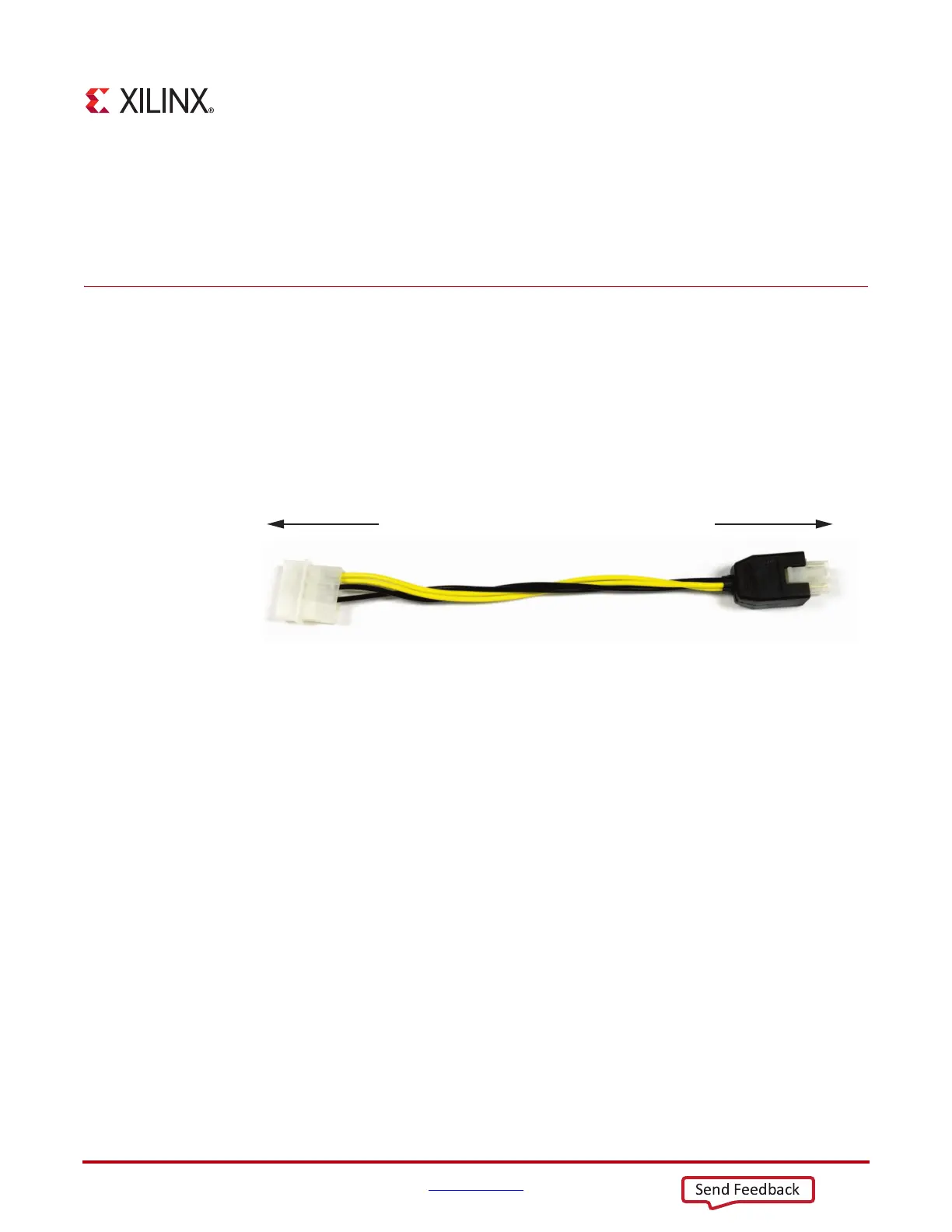
X-Ref Target - Figure D-1
Figure D-1: ATX Power Supply Adapter Cable
UG885_aD_01_092712
To ATX 4-Pin Peripheral
Power Connector
To J18 on VC707 Board

 Loading...


