50 www.xilinx.com VC707 Evaluation Board
UG885 (v1.4) May 12, 2014
Chapter 1: VC707 Evaluation Board Features
Status LEDs
[Figure 1-2, callout 21]
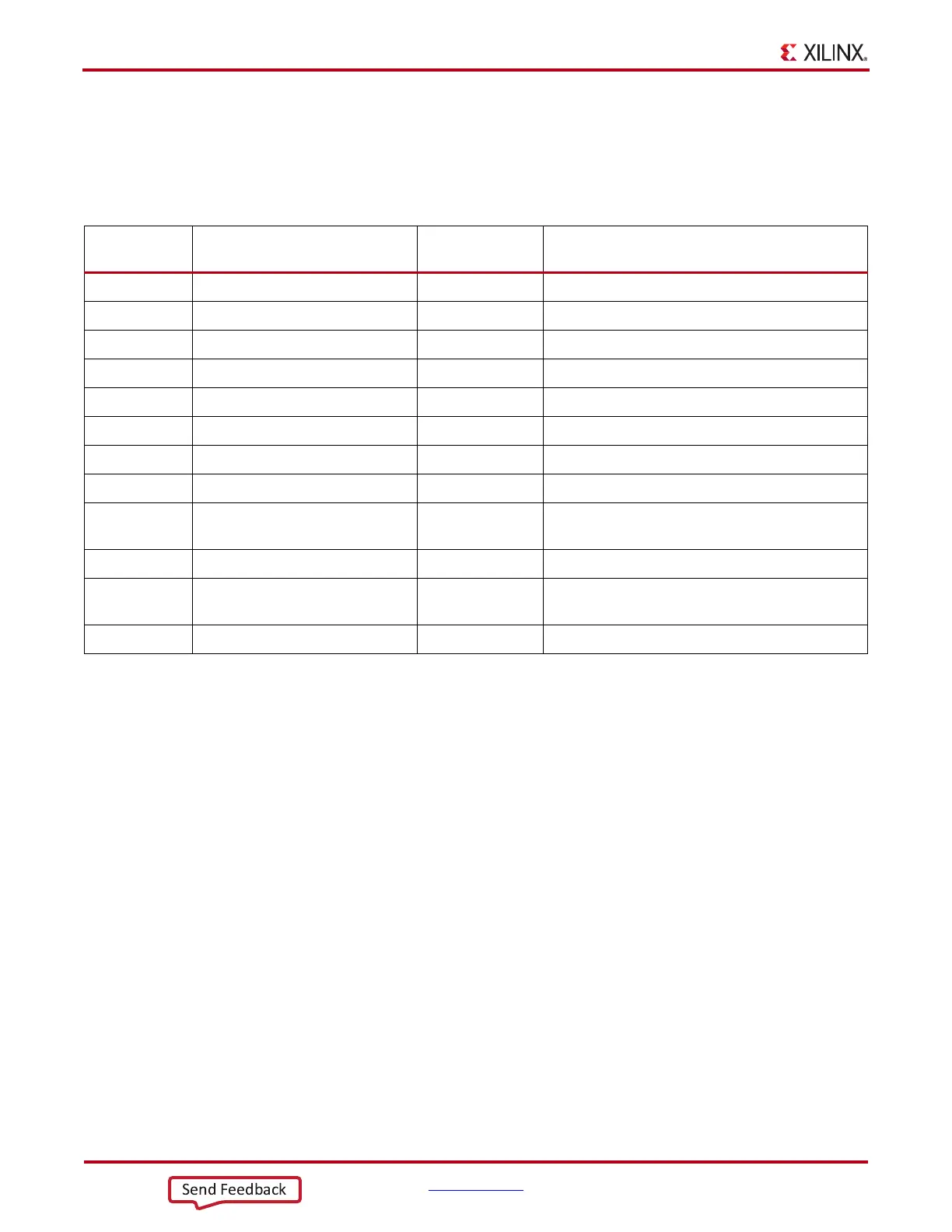
Table 1-25 defines the status LEDs. For user controlled LEDs see User I/O.
User I/O
[Figure 1-2, callout 22 - 26]
The VC707 board provides the following user and general purpose I/O capabilities:
• Eight user LEDs (callout 22)
• GPIO_LED_[7-0]: DS9, DS8, DS7, DS6, DS5, DS4, DS3, DS2
• Reset switch and five user pushbuttons (callout 23)
• CPU_RESET: SW8
• GPIO_SW_[NESWC]: SW3, SW4, SW5, SW7, SW6
• 8-position user DIP Switch (callout 24)
• GPIO_DIP_SW[7-0]: SW2
• User rotary switch (callout 25, hidden beneath the LCD)
• ROTARY_PUSH, ROTARY_INCA, ROTARY_INCB: SW10
• User SMA (callout 26)
• USER_SMA_GPIO_P, USER_SMA_GPIO_N: J33, J34
• 2 line x 16 character LCD character display (callout 19)
• If the display is unmounted, connector J23 pins are available as 7 independent
GPIOs. The LCD connector J23 details are shown in the LCD Character Display
(16 x 2) section.
Table 1-25: Status LEDs
Reference
Designator
Signal Name Color Description
DS11 PHY_LED_RX GREEN Ethernet PHY RX
DS11 PHY_LED_LINK1000 GREEN Ethernet Link Speed is 1000 Mb/s
DS12 PHY_LED_TX GREEN Ethernet PHY TX
DS12 PHY_LED_LINK100 GREEN Ethernet Link Speed is 100 Mb/s
DS13 PHY_LED_DUPLEX GREEN Ethernet Link is Half-duplex
DS13 PHY_LED_LINK10 GREEN Ethernet Link Speed is 10 Mb/s
DS14 PWRCTL1_VCC4A_PG GREENFMC1 HPC Power Good
DS10 FPGA_DONE GREEN FPGA Configured Successfully
DS1 FPGA_INIT_B GREEN/RED
GREEN: FPGA Initialization Successful,
RED: FPGA Initialization in Progress
DS16 VCC12_P_IN GREEN 12V Power ON
DS17 PWRCTL_PWRGOOD GREEN
UCD9248 Power Controllers (U42, U43, U64)
Power Good
DS18 LINEAR_POWER_GOOD GREEN TPS51200 Power Good (U23)

 Loading...


