40 www.xilinx.com VC707 Evaluation Board
UG885 (v1.4) May 12, 2014
Chapter 1: VC707 Evaluation Board Features
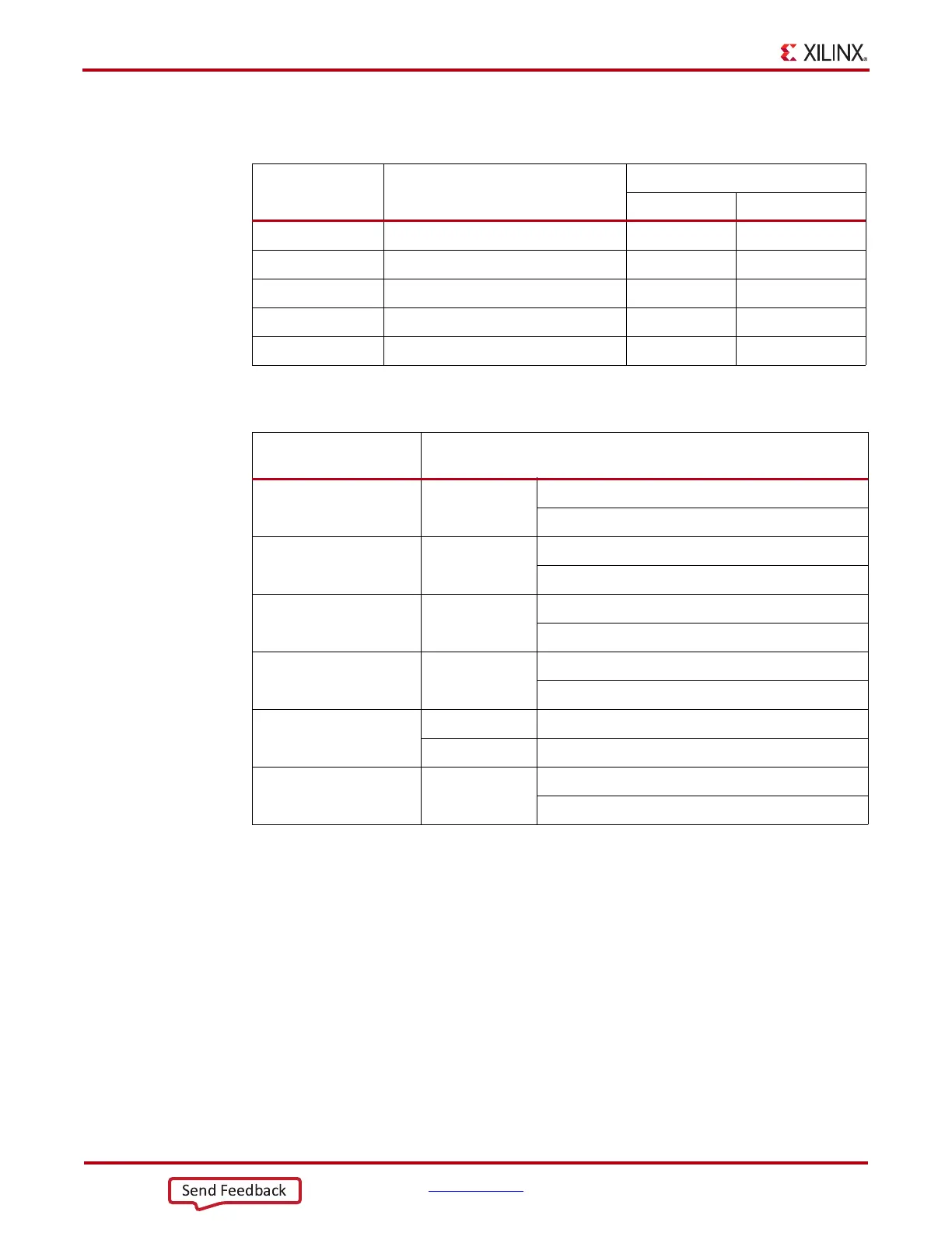
Table 1-15 lists the SFP+ module RX and TX connections to the FPGA.
Table 1-16 lists the SFP+ module control and status connections to the FPGA.
10/100/1000 Tri-Speed Ethernet PHY
[Figure 1-2, callout 15]
The VC707 board utilizes the Marvell Alaska PHY device (88E1111) U50 for Ethernet
communications at 10, 100, or 1000 Mb/s. The board supports SGMII mode only. The PHY
connection to a user-provided Ethernet cable is through a Halo HFJ11-1G01E RJ-45
connector (P4) with built-in magnetics.
On power-up, or on reset, the PHY is configured to operate in SGMII mode with PHY
address 0b00111 using the settings shown in Table 1-17. These settings can be overwritten
by software commands passed over the MDIO interface.
Table 1-15: FPGA U1 to SFP+ Module Connections
FPGA (U1) Pin Schematic Net Name
SFP+ Module (P3)
Pin Name
AL5 SFP_RX_N 12 RD_N
AL6 SFP_RX_P 13 RD_P
AM4 SFP_TX_P 18 TD_P
AM3 SFP_TX_N 19 TD_N
AP33 SFP_TX_DISABLE_TRANS 3 TX_DISABLE
Table 1-16: SFP+ Module Control and Status
SFP Control/Status
Signal
Board Connection
SFP_TX_FAULT Test Point J22 High = Fault
Low = Normal Operation
SFP_TX_DISABLE Jumper J6 Off = SFP Disabled
On = SFP Enabled
SFP_MOD_DETECT Test Point J21 High = Module Not Present
Low = Module Present
SFP_RS0 Jumper J38 Jumper Pins 1-2 = Full RX Bandwidth
Jumper Pins 2-3 = Reduced RX Bandwidth
SFP_RS1 Jumper J39 Jumper Pins 1-2 = Full TX Bandwidth
Jumper Pins 2-3 = Reduced TX Bandwidth
SFP_LOS Test Point J20 High = Loss of Receiver Signal
Low = Normal Operation

 Loading...


