VC707 Evaluation Board www.xilinx.com 43
UG885 (v1.4) May 12, 2014
Feature Descriptions
computer. The VCP device drivers must be installed on the host PC prior to establishing
communications with the VC707 board.
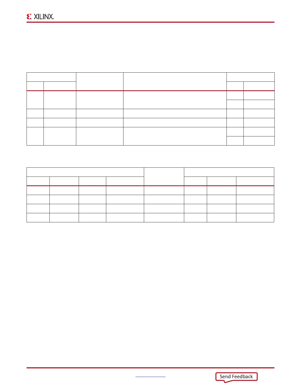
The USB Connector Pin Assignments and Signal Definitions between J17 and U44 are
listed in Table 1-19.
Table 1-20 shows the USB connections between the FPGA and the UART.
Refer to the Silicon Labs website for technical information on the CP2103GM and the VCP
drivers [Ref 19].
HDMI Video Output
[Figure 1-2, callout 18]
The VC707 board provides a High-Definition Multimedia Interface (HDMI™) video
output using the Analog Devices ADV7511KSTZ-P HDMI transmitter (U48). The HDMI
output is provided on a Molex 500254-1927 HDMI type-A connector (P2). The ADV7511 is
wired to support 1080P 60 Hz YCbCr and RGB video modes through 36-bit input data
mapping.
The VC707 board supports the following HDMI device interfaces:
• 36 data lines
• Independent VSYNC, HSYNC
• Single-ended input CLK
• Interrupt Out Pin to FPGA
•I
2
C
•SPDIF
Table 1-19: USB Connector J17 Pin Assignments and Signal Definitions
USB Connector (J17)
Net Name Description
CP2103GM (U44)
Pin Name Pin Name
1 VBUS USB_UART_VBUS +5V VBUS Powered
7REGIN
8VBUS
2 D_N USB_D_N Bidirectional differential serial data (N-side) 4 D –
3 D_P USB_D_P Bidirectional differential serial data (P-side) 3 D +
4 GND USB_UART_GND Signal ground
2GND1
29 CNR_GND
Table 1-20: FPGA to UART Connections
FPGA (U1)
Schematic Net
Name
CP2013 Device (U12)
Pin Function Direction IOSTANDARD Pin Function Direction
AR34 RTS Output LVCMOS18 USB_CTS 22 CTS Input
AT32 CTS Input LVCMOS18 USB_RTS 23 RTS Output
AU36 TX Output LVCMOS18 USB_RX 24 RXD Input
AU33 RX Input LVCMOS18 USB_TX 25 TXD Output

 Loading...


