Virtex-5 RocketIO GTP Transceiver User Guide www.xilinx.com 205
UG196 (v1.3) May 25, 2007
Analog Design Guidelines
R
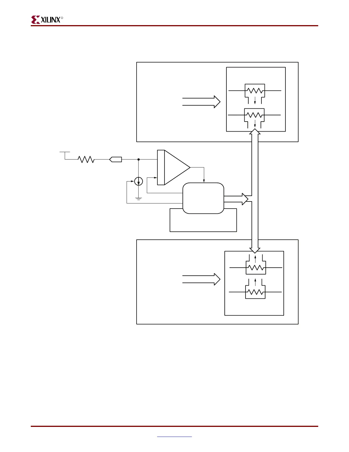
The calculated calibration value of the resistor calibration circuit is shared between all
GTP_DUAL primitives of a device (see Figure 10-5).
The resistor calibration is performed automatically one time during the configuration
process. All analog supply voltages must be present and within the proper tolerance as
specified in the Virtex-5 Data Sheet.
This value can be overwritten independently for each transceiver by using the
TERMINATION_CTRL and TERMINATION_OVRD attributes. This feature is intended for
experimental purposes only.
Figure 10-5: Calibration Result Sharing Between All GTP_DUAL Tiles
Notes:
1. This analog supply must be sourced directly from the closest MGTAVTTTX device pin.
MGTAVTTTX
(1)
RREF
External 50 Ω
Precision Resistor
MGTRREF
Package Pin
Other GTP_DUAL Tiles North of the Center
Other GTP_DUAL Tiles South of the Center
“Master” GTP_DUAL Tile
for Resistor Calibration
Override/Offset
Code
Internal Resistor
Network
Comparator
UG196_c10_05_041907
Override/Offset
Code
BRcal
rCtrl[0:4]
RX/TX
Termination
RX/TX
Termination
 Loading...
