Virtex-5 RocketIO GTP Transceiver User Guide www.xilinx.com 149
UG196 (v1.3) May 25, 2007
Configurable Comma Alignment and Detection
R
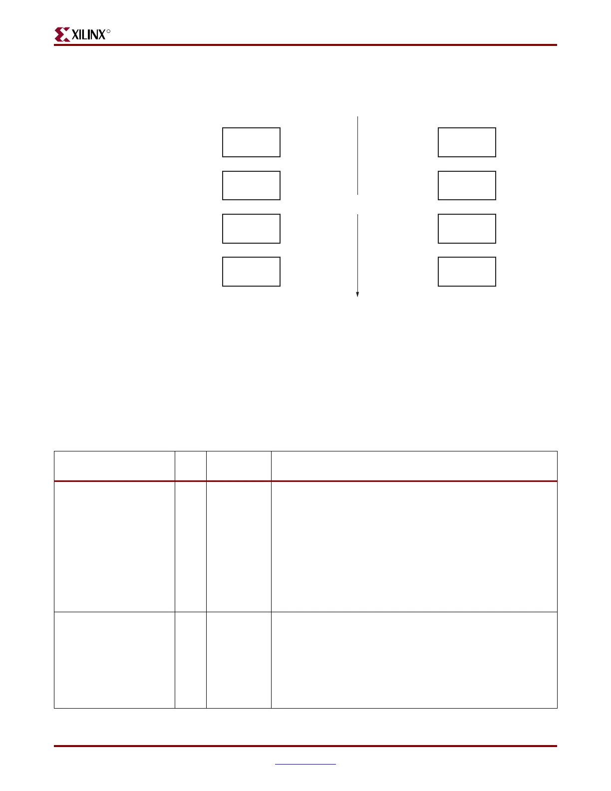
Figure 7-11 shows the TX parallel data is on the left side, and the RX receiving recognizable
parallel data is on the right side.
The GTP transceiver includes an alignment block that can be programmed to align specific
commas to various byte boundaries, or to manually align data using attribute settings (see
Table 7-21, page 151). SONET A1A2 alignment is possible using comma double mode. The
block can be bypassed to reduce latency if it is not needed.
Ports and Attributes
Table 7-20 defines the RX comma alignment and detection ports.
Figure 7-11: Parallel Data View of Comma Alignment
TX Parallel Data RX Parallel Data
Data0
Comma
Data1
Data2
?????
Comma
Data1
Data2
Time
UG96_c7_11_092606
Table 7-20: RX Comma Alignment and Detection Ports
Port Dir
Clock
Domain
Description
RXBYTEISALIGNED0
RXBYTEISALIGNED1
Out RXUSRCLK2
Signal from comma detection and realignment circuit. Stays High
to indicate that the parallel data stream is properly aligned on byte
boundaries according to comma detection.
0: Parallel data stream not aligned to byte boundaries
1: Parallel data stream aligned to byte boundaries
There will be several cycles after RXBYTEISALIGNED is asserted
before aligned data is available at the FPGA RX interface.
RXBYTEISALIGNED responds to plus comma alignment when
PCOMMA_ALIGN is TRUE. RXBYTEISALIGNED responds to
minus comma alignment when MCOMMA_ALIGN is TRUE.
RXBYTEREALIGN0
RXBYTEREALIGN1
Out RXUSRCLK2
Signal from comma detection and realignment circuit indicating
that the byte alignment within the serial data stream has changed
due to a comma detection.
0: Byte alignment has not changed
1: Byte alignment has changed
Data can be lost when alignment occurs, which can cause data
errors (and disparity errors when the 8B/10B decoder is used).
 Loading...

