Virtex-5 RocketIO GTP Transceiver User Guide www.xilinx.com 87
UG196 (v1.3) May 25, 2007
Dynamic Reconfiguration Port (DRP)
R
Dynamic Reconfiguration Port (DRP)
Overview
The DRP allows the dynamic change of parameters of the GTP_DUAL tile. The DRP
interface is a processor-friendly synchronous interface with an address bus (DADDR) and
separated data buses for reading (DO) and writing (DI) configuration data to the
GTP_DUAL tile. An enable signal (DEN), a read/write signal (DWE), and a ready/valid
signal (DRDY) are the control signals that implement read and write operations, indicate
operation completion, or indicate the availability of data.
Ports and Attributes
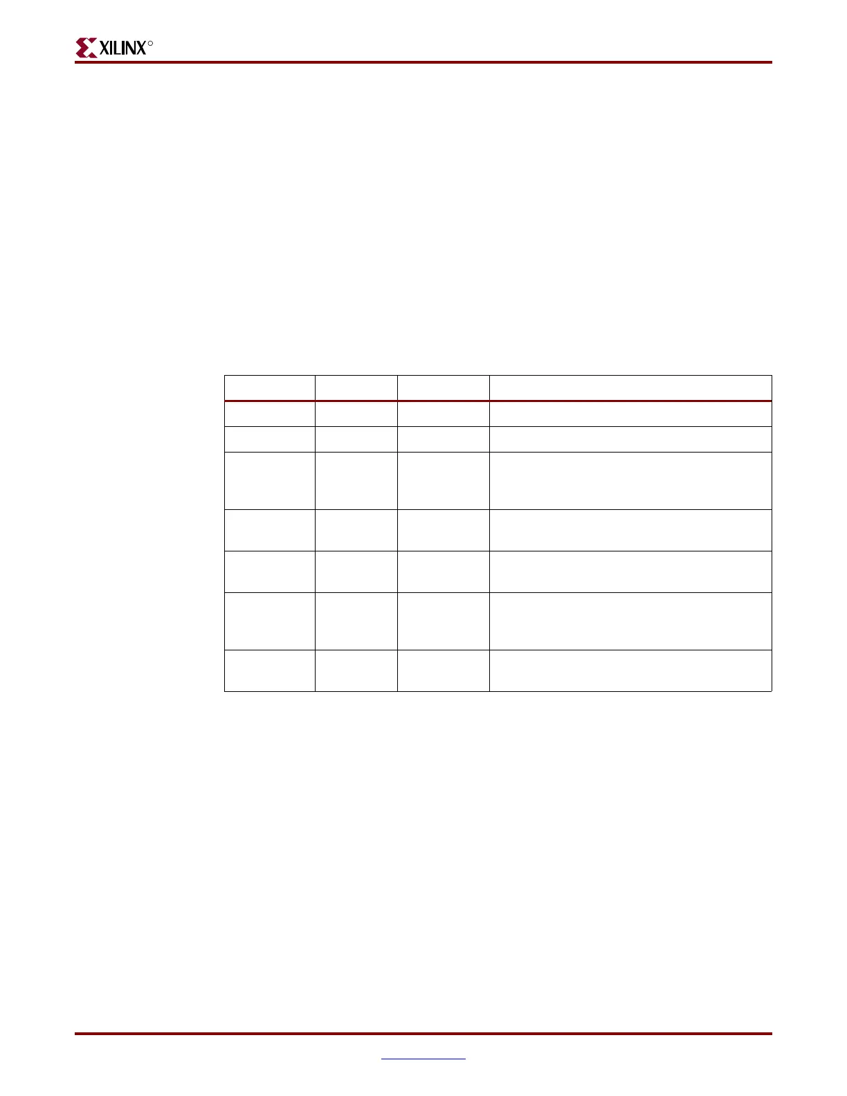
Table 5-14 defines the DRP signals.
There are no attributes in this section.
Description
The Virtex-5 Configuration Guide provides detailed information on the DRP interface. Refer
to Appendix D, “DRP Address Map of the GTP_DUAL Tile,” for a map of GTP_DUAL
DRP attributes sorted alphabetically by name and by address.
Stopping the reference clock during a DRP operation can prevent the correct termination of
the operation.
Table 5-14: DRP Ports
Port Dir Clock Domain Description
DADDR[6:0] In DCLK DRP address bus
DCLK
In N/A DRP interface clock
DEN In DCLK
Set to 1 to enable a read or write operation. Set
to 0 on DCLK cycles where no operation is
required.
DI[15:0]
In DCLK
Data bus for writing configuration data from
the FPGA fabric to the GTP_DUAL tile.
DO[15:0]
Out DCLK
Data bus for reading configuration data from
the GTP_DUAL tile to the FPGA fabric.
DRDY
Out DCLK
Indicates operation is complete for write
operations and data is valid for read
operations.
DWE In DCLK
Set to 0 for read operations. Set to 1 for write
operations.
 Loading...
