Virtex-5 RocketIO GTP Transceiver User Guide www.xilinx.com 75
UG196 (v1.3) May 25, 2007
Reset
R
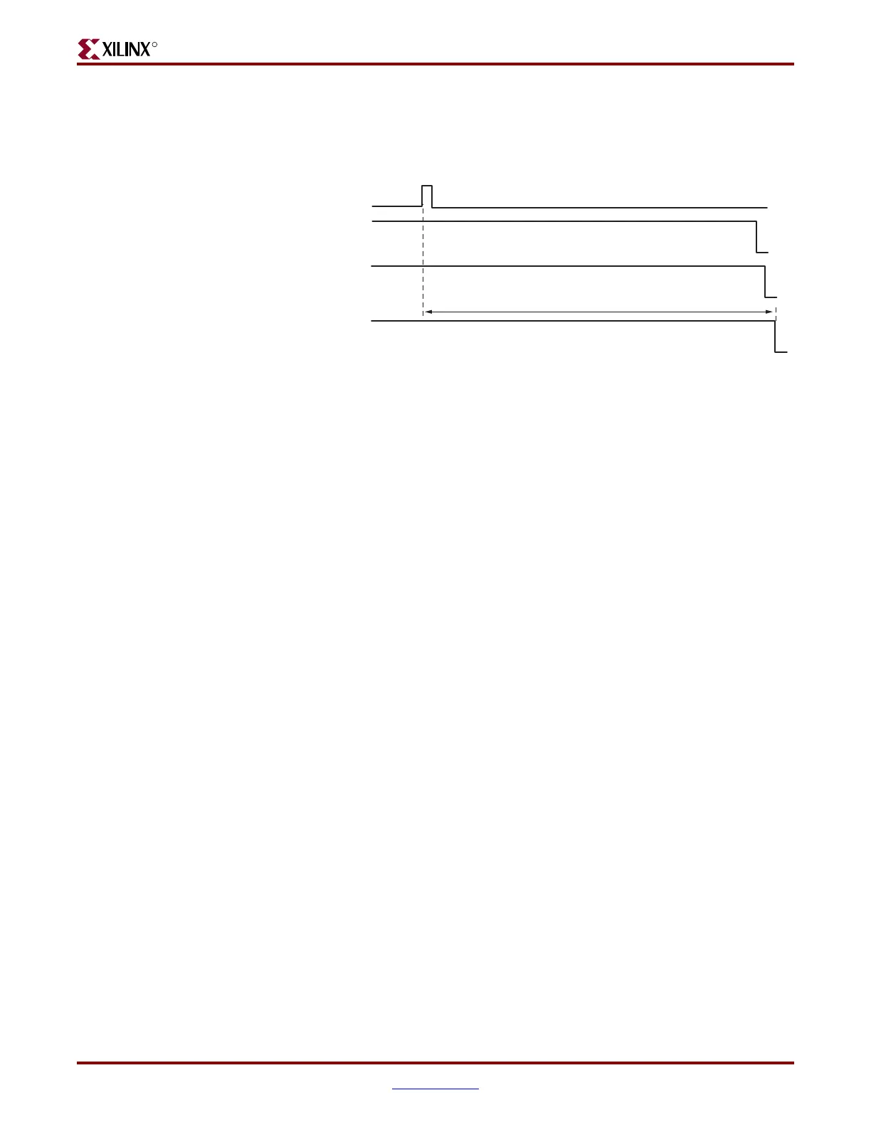
GTP Reset When the GTPRESET Port is Asserted
Figure 5-8 is similar to Figure 5-7, showing the full reset sequence occurring in response to
a pulse on GTPRESET. GTPRESET acts as an asynchronous reset signal.
The following GTP_DUAL sections are affected by the GTPRESET sequence:
• Shared PMA PLL
• GTP0 transmit section (PMA and PCS)
• GTP0 receive section (PMA and PCS)
• GTP1 transmit section (PMA and PCS)
• GTP1 receive section (PMA and PCS)
GTP Component-Level Resets
Component resets are primarily used for special cases. These resets are needed when only
the reset of a specific GTP_DUAL subsection is required. Table 5-6, page 73 provides an
overview of component level resets. Table 5-7 describes the component level resets.
All component resets are asynchronous with the exception of PRBSCNTRESET, which is
synchronous to RXUSRCLK2 and is effective only on its rising edge.
Link Idle Reset Support
During operation, an electrical idle condition can occur on the GTP receiver, causing
RXELECIDLE to be driven High. The following events can cause an RX electrical idle
condition:
• An open RXP/RXN differential input pair
• A transmitter on the other side of the communication link powers down
• An OOB/beacon signaling sequence
During an electrical idle condition the Clock Data Recovery (CDR) circuit in the receiver
can lose lock. To restart the CDR after an electrical idle condition, RXELECIDLERESET and
RXENELCIDLERESETB must be asserted. “RX Clock Data Recovery (CDR),” page 136
describes the RXELECIDLERESET, RXENELECIDLERESETB, and the CDR circuit in more
detail.
Figure 5-8: Reset Sequence Triggered by the GTPRESET Pulse
~160 μs
UG196_c5_08_100606
Internal RXBUFRESET
Internal RXRESET
Internal TXRESET
GTPRESET
 Loading...
